Manufacturing method of support frame of display panel, support frame of display panel and display device

a technology of display panel and support frame, which is applied in the direction of identification means, instruments, television systems, etc., can solve the problems of reduced yield, long working hours, and additional special equipment to be prepared

Inactive Publication Date: 2005-02-22
VISTA PEAK VENTURES LLC
View PDF4 Cites 1 Cited by
  • Summary
  • Abstract
  • Description
  • Claims
  • Application Information

AI Technical Summary

Benefits of technology

With still another configuration as above, a first component member made of a metal and making up a side portion of the support frame having convex portions and concave portions arranged alternately at its end portion in a manner that each of the convex portions and the concave portions is bilaterally symmetrical, while a shear droop and a burr are formed at each end portion of each of the plurality of component members is taken out from a plate material. Then, the convex portions making up an end portion of a second component member made of a resin making up a corner of the support frame and having the convex portions and concave portions arranged alternately and having a positioning portion on its upper surface to be used for attaching the display panel to a predetermined place and the concave portions making up an end portion of the first component members in a manner that each of the convex portions and the concave portion is bilaterally symmetrical, are placed in such a manner that the shear droop of each of the convex portions faces the burr of each of the concave portions the burr of each of the convex portions faces the shear droop of each of the concave portions and, while the end portion of the first component member is pushed toward the end portion of the second component member, by pressing the convex and concave portions in upward and downward directions using a pair of metal molds on which projected portions are formed on a surface of one of the metal molds in a position being apart by a specified distance from the end portion of the first component member, thus causing end portions of a plurality of component members to be fitted and coupled. Therefore, it is possible to perform positioning of the display panel in small component counts and in small numbers of processes.

Problems solved by technology

However, the first conventional example has a disadvantage in that, since the melting and bonding processes are included in the method of manufacturing the support frame for the display panel provided in the first conventional example, generally, long working hours are required.
Another problem is that, when a laser deposition method is used for the melting and bonding processes, in particular, additional special equipment has to be prepared.
On the other hand, the method for manufacturing the support frame for the display panel provided in the second conventional example also has a disadvantage in that, since the formation of the constricted portions 14c and 15c is necessary, if hardness of the employed component member is very high, it is difficult to form such the constricted portions 14c and 15c precisely.
This means that, in the second conventional example, types of component members or manufacturing conditions that can be applied are limited and, if types of the component members are erroneously selected or the manufacturing conditions are erroneously set, defectives continuously occur and a yield is decreased, as a result.
Furthermore, in the case of the second conventional example, after the plane pierce-shaped convex portions 14a and 15a and the plane pierce-shaped concave portions 14b and 15b are mechanically fitted, process of crimping the fitting / coupling sections 14 and 15 from upward and downward directions using the pressing machine is needed, which causes low productivity in manufacturing the support frame.
However, iron has a high specific gravity and high hardness and, therefore, when it is used for a large screen, a weight of a display device becomes high and iron is difficult to be processed.
Aluminum has also a disadvantage because it is expensive.
Therefore, a process of pasting up the copper foil is additionally required which causes an increase in component counts and in the number of processes.
As a result, a process of pasting up the insulator 16 is additionally required which causes an increase in component counts and in the number of processes.
Therefore, a process of mounting the positioning member 7 is additionally required which also causes an increase in component counts and in the number of processes.

Method used


Image

  • Manufacturing method of support frame of display panel, support frame of display panel and display device
  • Manufacturing method of support frame of display panel, support frame of display panel and display device
  • Manufacturing method of support frame of display panel, support frame of display panel and display device

Examples


first embodiment

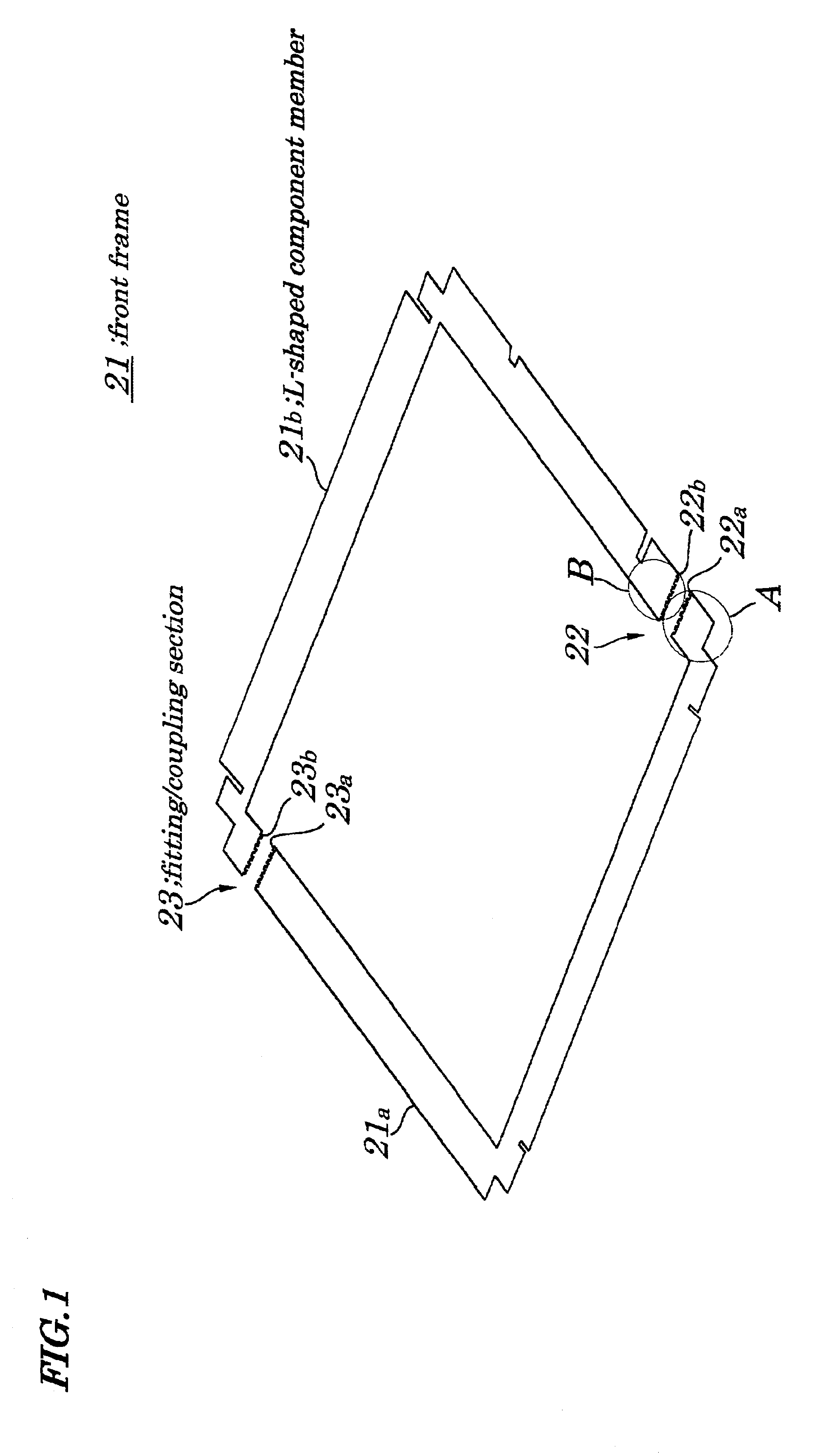
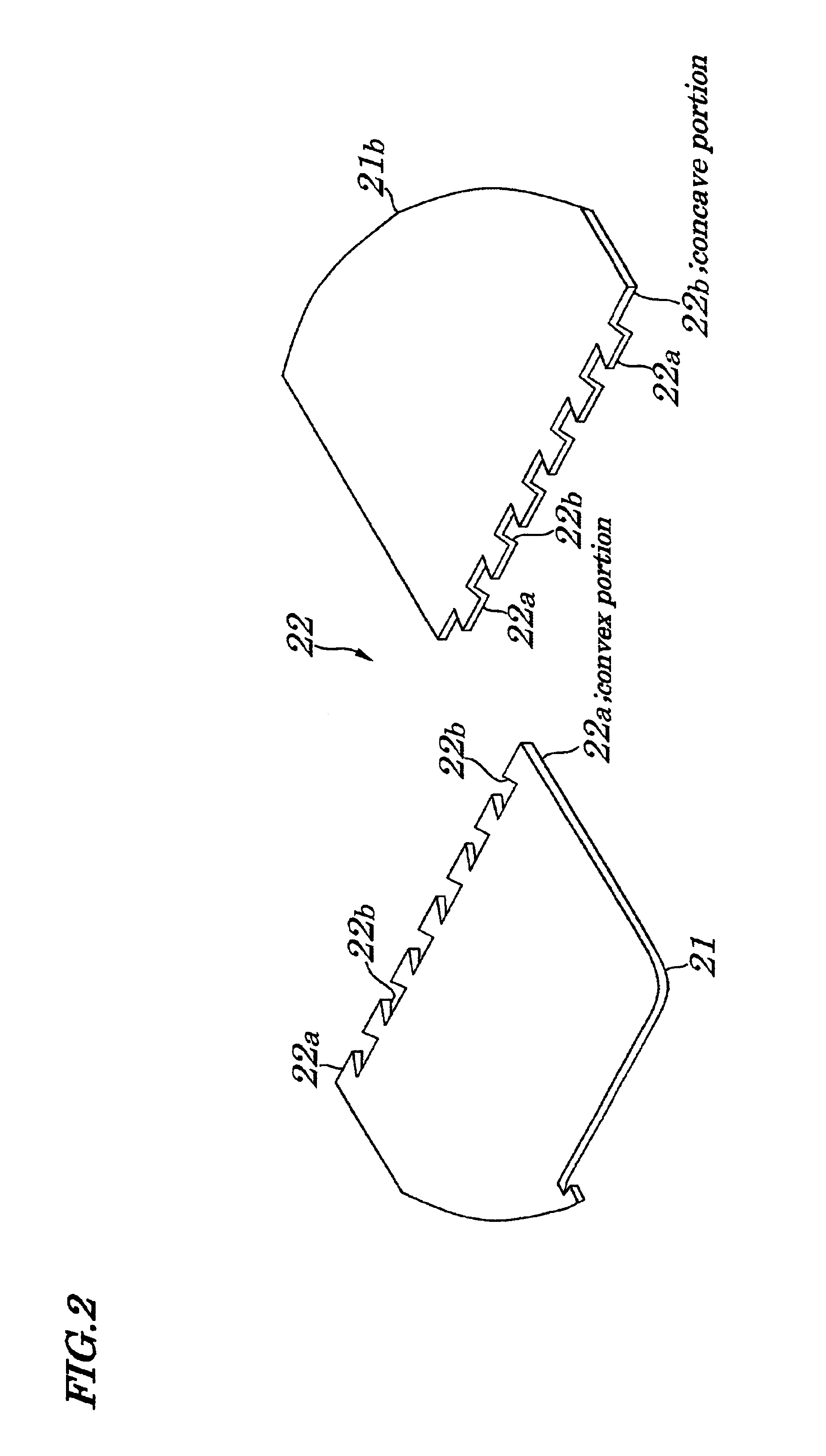
FIG. 1 is an exploded perspective view showing L-shaped component members 21a and 21b making up a front frame 21 in a developed state according to a first embodiment of the present invention. The front frame 21 of the first embodiment is assembled so as to have an approximately ç-shaped configuration and is made up of two L-shaped component members 21a and 21b each end portion of which is disposed in a position being slightly apart from each of corner portions in a manner so as to have an approximately L-shaped configuration. Moreover, a fitting / coupling section 22 having convex portions 22a and concave portions 22b each of the convex portions 22a and concave portions 22b having a trapezoidal configuration is provided at a place where the L-shaped component member 21a is coupled to the L-shaped component member 21b and another fitting / coupling section 23 having convex portions 23a and concave portions 23b each of the convex portions 23a and concave portions 23b having a trapezoidal ...

second embodiment

FIGS. 8A, 8B, and 8C are process diagrams explaining a method for fabricating a front frame 21 (FIG. 1) according to a second embodiment of the present invention. In FIGS. 8A, 8B, and 8C, same reference numbers are assigned to corresponding parts having same functions as those shown in FIGS. 6A, 6B, and 6C and their descriptions are omitted accordingly. In FIGS. 8A, 8B, and 8C, instead of a lower metal mold 29 and an upper metal mold 30 shown in FIGS. 6A, 6B, and 6C, a lower metal mold 33 and an upper metal mold 34 are newly provided. As a material for the lower metal mold 33 and upper metal mold 34, hardened steel called “alloyed tool steel” is generally used. A line-shaped projected portion 33a is formed on an upper surface of the lower metal mold 33 in a position being opposite to an L-shaped component member 21b and in parallel to an end face of the L-shaped component member 21b and in a place being apart by a specified distance from the end face of the L-shaped component member...

third embodiment

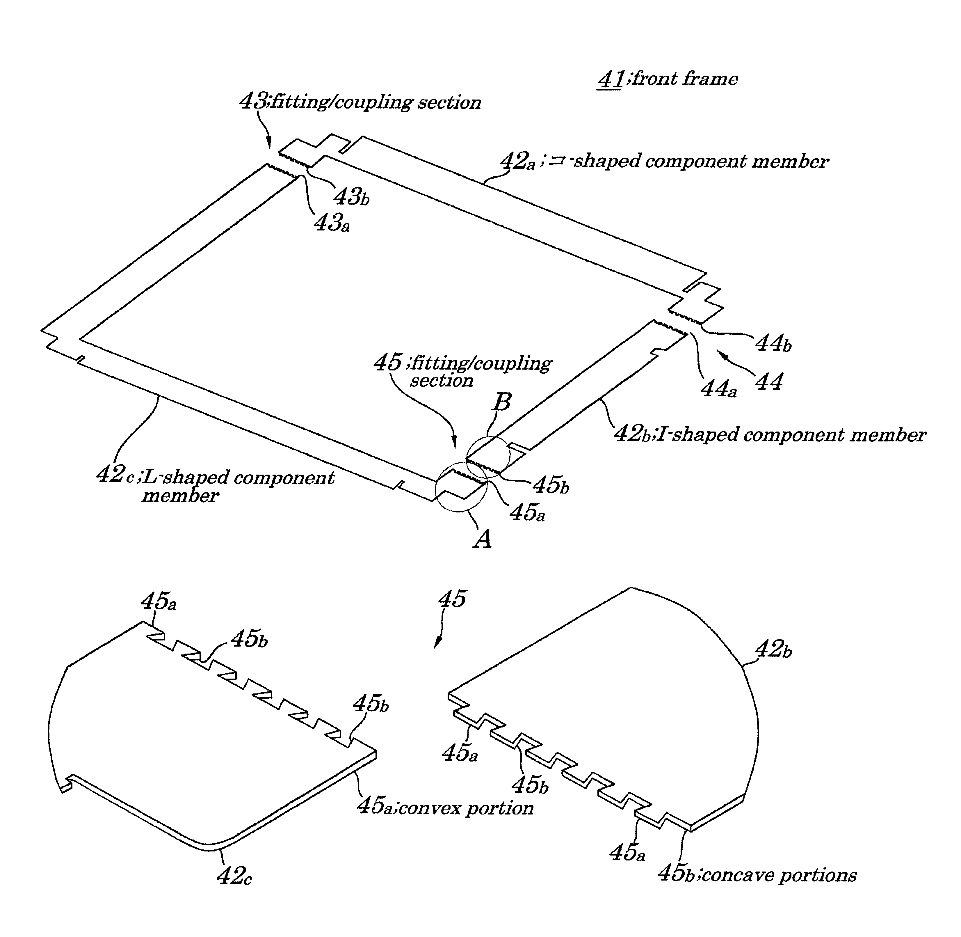
FIG. 9 is an exploded perspective view of a -shaped component member 42a. an I-shaped component member 42b, and an L-shaped component member 42c making up a front frame 41 in a developed state according to a third embodiment of the present invention.

The front frame 41 of the third embodiment is assembled so as to have an approximately □-shaped configuration and is made up of an approximately -shaped component member 42a making up its upper portion, an approximately I-shaped component member 42b making up its right side portion, and an approximately L-shaped component member 42c making up its left side portion and its lower portion. A fitting / coupling section 43 having trapezoidal convex portions 43a and trapezoidal concave portions 43b is provided at a place where the -shaped component member 42a is coupled to the approximately L-shaped component member 42c, a fitting / coupling section 44 having trapezoidal convex portions 44a and trapezoidal concave portions 44b is provided at a pla...


PUM

PropertyMeasurementUnit
frequencyaaaaaaaaaa
specific gravityaaaaaaaaaa
thicknessaaaaaaaaaa

Abstract

A method is provided for manufacturing a support frame of a rectangular display panel within a short working time. The method includes a process of taking out L-shaped component members each having convex portions and concave portions arranged alternately at an end portion in a manner that each of the convex portions and concave portions is bilaterally symmetrical, while a shear droop and a burr are formed on an end portion and process of fitting and coupling end portions of L-shaped component members by placing the convex portions and the concave portions in such a manner that the shear droop of each of the convex portions faces the burr of each of the concave portions and the burr of each of the convex portions faces the shear droop of each of the concave portions and that that the convex portions and the concave portions are pushed towards each other and by pressing the convex portions and the concave portions using a pair of metal molds.

Description

BACKGROUND OF THE INVENTION1. Field of the InventionThe present invention relates to a method for manufacturing a support frame of a display panel being used as a display device for personal computers, TV (television) sets, or a like; and more particularly to the method of manufacturing the support frame of the rectangular display panel which is used to support a portion surrounding the rectangular display panel and to the support frame of the rectangular display panel manufactured by the above method and to the display device equipped with the above support frame.The present application claims priority of Japanese Patent Application No.2001-088848 filed on Mar. 26, 2001, which is hereby incorporated by reference.2. Description of the Related ArtAs a rectangular display panel, an LCD (Liquid Crystal Display) panel, a PDP (Plasma Display Panel), or panels made up of light emitting elements such as an EL (Electroluminescence), an LED (Light Emitting Diode), a VFD (Vacuum Fluorescent D...

Claims


Application Information

Patent Timeline
Patent Type & Authority Patents(United States)
IPC IPC(8): G02F1/13G06F1/16H04N5/64G02F1/1333G09F9/00
CPCG02F1/133308G06F1/1601B29C65/56B29C65/7841B29C66/1284B29C66/12861B29C66/14B29C66/2274B29C66/43B29C66/81427B29C66/8322Y10T29/49826G02F2001/133325G02F2001/133328G06F2200/1612B29L2012/00B29C65/564B29C66/2272B29L2031/3475B29C66/81417Y10T29/49885G02F2001/133322G02F1/133322G02F1/133325G02F1/133328G02F1/1333
Inventor FUJISHIRO, FUMIHIKOFUKUYOSHI, HIROKAZU
Owner VISTA PEAK VENTURES LLC
Why Eureka
Try Eureka