
Methods for preparing electrolyte membrane and electrolyte membrane/electrode assembly for fuel cells

a fuel cell and electrolyte technology, applied in the direction of electrochemical generators, sustainable manufacturing/processing, final product manufacturing, etc., can solve the problems of increased cost of fluororesin base electrolyte membranes as typified by nafion, lack of practical usefulness of electrolyte membranes, and substantial bar against practical applications, etc., to achieve the effect of reducing thickness

Inactive Publication Date: 2009-12-08
SHIN ETSU CHEM IND CO LTD
View PDF12 Cites 0 Cited by
  • Summary
  • Abstract
  • Description
  • Claims
  • Application Information

AI Technical Summary

Benefits of technology

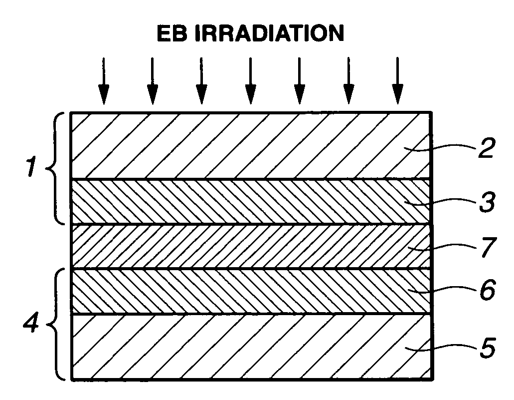
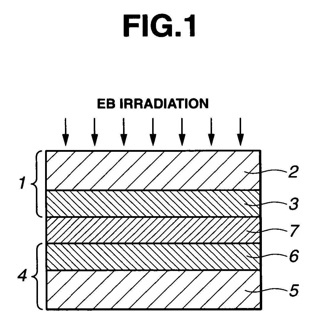
The present invention provides methods for preparing electrolyte membranes and electrolyte membrane / electrode assemblies for fuel cells with improved characteristics of proton conduction, elongation, and strength. The methods involve irradiating a liquid proton-conductive compound with radiation to form a cured film, which can be used as an electrolyte membrane. The membrane can be tightly bonded to the electrodes without the need for hot pressing, and the resulting assembly has high proton conductivity and satisfactory elongation and strength. The methods are efficient and can produce electrolyte membranes with reduced thickness, making them useful in various types of fuel cells.

Problems solved by technology

These electrolyte membranes, however, lacked practical usefulness due to very low durability.
One problem associated with conventional fluororesin base electrolyte membranes as typified by Nafion is an increased cost because their manufacture starts from the synthesis of monomers and requires a number of steps.
This becomes a substantial bar against practical applications.
However, none of these electrolyte membranes have better characteristics of proton conduction, elongation and strength than Nafion.

Method used


Image

  • Methods for preparing electrolyte membrane and electrolyte membrane/electrode assembly for fuel cells
  • Methods for preparing electrolyte membrane and electrolyte membrane/electrode assembly for fuel cells

Examples


example 1

[0067]A reactor was charged with 60 g of a nonylphenol EO (4 mole)-modified acrylate, Aronix M-113 (Toagosei Co., Ltd., trade name), 88.6 g of polyethylene glycol having a number average molecular weight of 1,000, and 0.1 g of 2,6-di-tert-butylhydroxytoluene. In a nitrogen stream at 65-70° C., 30.8 g of 2,4-tolylene diisocyanate was added dropwise to the reactor. After the completion of dropwise addition, the reactor was kept at 70° C. for 2 hours, followed by addition of 0.02 g of dibutyltin dilaurate. In dry air, 20.6 g of 2-hydroxyethyl acrylate was added dropwise. The reactor was kept at 70° C. for a further 5 hours, obtaining a polyether urethane acrylate oligomer containing 30% by weight of M-113 (Oligomer A).

[0068]50 parts by weight of Oligomer A was mixed with 50 parts by weight of phospho-tungstate n-hydrate (by Wako Junyaku Industry Co., Ltd.) to form a liquid electrolyte membrane composition having a viscosity of 12,000 mPa·s at 25° C.

[0069]Next, a 5% isopropyl alcohol so...


PUM

PropertyMeasurementUnit
operating temperatureaaaaaaaaaa
viscosityaaaaaaaaaa
viscosityaaaaaaaaaa

Abstract

An electrolyte membrane for fuel cells is prepared by irradiating with radiation a composition comprising a radiation-curable liquid compound having proton conductivity for curing the liquid compound to form a cured film. The methods of the invention are successful in producing an electrolyte membrane and an electrolyte membrane / electrode assembly for fuel cells while satisfying both the requirements of productivity and cell-related properties including proton conduction and membrane strength.

Description

CROSS-REFERENCE TO RELATED APPLICATION[0001]This non-provisional application claims priority under 35 U.S.C. §119(a) on Patent Application No. 2003-357928 filed in Japan on Oct. 17, 2003, the entire contents of which are hereby incorporated by reference.TECHNICAL FIELD[0002]This invention relates to methods for preparing an electrolyte membrane having improved properties of proton conduction and strength and an electrolyte membrane / electrode assembly for solid polymer electrolyte fuel cells.BACKGROUND ART[0003]Fuel cells using solid polymer electrolyte (SPE) membranes are expected to find widespread use as power supplies for electric cars and small-size auxiliary power supplies due to a low operating temperature below 100° C. and a high energy density. In such SPE fuel cells, constituent technologies relating to electrolyte membranes, platinum base catalysts, gas diffusion electrodes, and electrolyte membrane / electrode assemblies are important. Among others, the technologies relatin...

Claims


Application Information

Patent Timeline
Patent Type & Authority Patents(United States)
IPC IPC(8): B05D5/12C08J5/22H01M8/02H01M8/10
CPCC08J5/2293H01M8/1004H01M8/1081C08J2327/12H01M2300/0082Y02E60/521Y02E60/50Y02P70/50
Inventor OHBA, TOSHIOKONISHI, SHIGERUTAKAHASHI, MITSUHITOTAKAHASHI, NORIFUMI
Owner SHIN ETSU CHEM IND CO LTD
Learn More