Heat pipes incorporating microchannel heat exchangers

a heat exchanger and microchannel technology, applied in indirect heat exchangers, solar heat systems, lighting and heating apparatus, etc., can solve the problems of limiting the performance of heat pipes, the rate of heat transfer into the heat absorber, and/or the heat transfer rate from the heat sink to the cooling medium

Active Publication Date: 2009-09-17
QCIP HLDG
View PDF45 Cites 62 Cited by
  • Summary
  • Abstract
  • Description
  • Claims
  • Application Information

AI Technical Summary

Benefits of technology

[0035]transferring at least some of the heat from the photovoltaic solar cell to a working fluid in a plurality of microchannels having a cross-sectional dimension to the center of the channel that is about equal to or less than the thermal boundary layer thickness for the working fluid,

Problems solved by technology

The rate of heat transfer into the heat absorber, and / or the rate of heat transfer from the heat sink to the cooling medium, is often the limiting factor in the performance of heat pipes, especially if the ratio of the fluid internal surface area to the working fluid volume is relatively small in the absorber or the heat sink

Method used


Image

  • Heat pipes incorporating microchannel heat exchangers
  • Heat pipes incorporating microchannel heat exchangers
  • Heat pipes incorporating microchannel heat exchangers

Examples


example 1

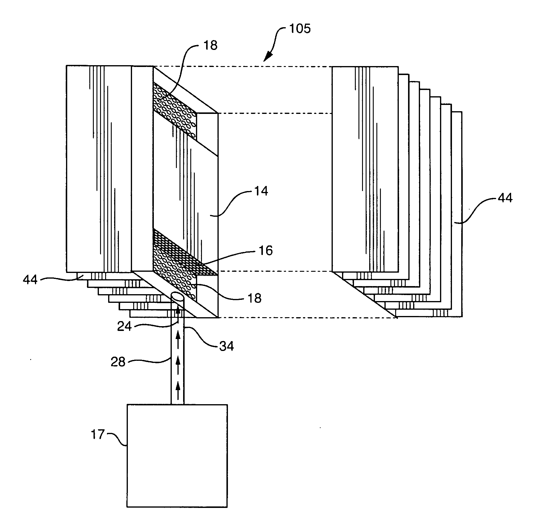
Air-Cooled Single-Tube Non-Wick Heat Pipe System

[0086]A heat pipe system is constructed, consisting of a microchannel block-type heat absorber, a finned microchannel heat sink, a connecting pipe, and a working fluid. The heat absorber is an Atotech “Ardex MC-1” microchannel CPU cooler, manufactured by Atotech Deutschland GmbH of Berlin, Germany. One of the two threaded ports is provided with a male adapter ⅜″ tube fitting. The other threaded port is closed off with a pipe plug. The heat sink is an Atotech “Ardex MC-1” microchannel CPU cooler, modified by the addition of thin sheet metal copper cooling fins soldered to the flat side of the MC-1 device. One of the two threaded ports is provided with a male adapter ⅜″ tube fitting. The other threaded port is closed off with a pipe plug. The connecting pipe is a ⅜″ diameter semi-flexible copper or perfluoroalkoxy (PFA) plastic tube, connected to the absorber and heat sink by means of the tube fittings. The connecting pipe is preferably ...

example 2

Air-Cooled Two-Tube Non-Wick Heat Pipe System

[0092]A heat pipe system was constructed, consisting of an Atotech Ardex P microchannel block-type heat absorber, a finned microchannel heat sink, two connecting pipes, and a working fluid. The microchannel heat sink consisted of an Atotech Ardex P microchannel block soldered to a CompUSA Pentium 4 Socket 478 CPU cooler fin-fan assembly. The heat pipe assembly consisted of substantially the same equipment and construction as used in Example 1, with the following differences. The second port of the heat absorber was provided with a ¼″ tube fitting male run tee, in lieu of the pipe plug. The second port of the heat sink was provided with a male adapter ¼″ tube fitting, in lieu of the pipe plug. Two connecting pipes were used. The vapor pipe was a ⅜″ diameter PFA tube, and the liquid pipe was a ¼″ PFA tube. The connecting tubes were connected to the absorber by means of the tube fittings on the heat absorber and the heat sink. The working fl...

example 3

Liquid-Cooled Single-Tube Heat Pipe System

[0096]A heat pipe system is constructed, consisting of a microchannel block-type heat absorber, a water-cooled microchannel heat exchanger heat sink, a connecting pipe, and a working fluid. The heat pipe assembly consists of substantially the same equipment as described in Example 2, with the following differences. The heat sink is a cross-flow 2-fluid microchannel heat exchanger. The working fluid is the first fluid, and flowing cooling water is the second fluid, so that heat is removed from the system by heat transfer from the condensing working fluid vapors, through the walls of the microchannel heat sink, into the cooling water.


PUM


Abstract

A heat pipe can include a microchannel heat exchanger at the heat absorbing end and another heat exchanger which is optionally also a microchannel heat exchanger at the heat sink end, with one or more pipes flowably connecting the two ends for transporting liquid working fluid to the head absorber and vaporized working fluid to the heat sink. The heat pipes may be used to cool electronic devices with rejection of heat outside an enclosure, and optionally outside a room, containing the electronic devices. The heat pipes may be used to cool photovoltaic or solar collection devices with rejection of heat to ambient air at a distance removed from the photovoltaic devices. Heat pipe systems are disclosed wherein the working fluid is a hydrofluorocarbon or a mono-chlorinated hydrofluoroalkene having a normal boiling point in a range from 10° C. to 80° C.

Description

CROSS REFERENCE TO RELATED APPLICATION[0001]This application claims the benefit under 35 U.S.C. 119(e) of U.S. provisional application Ser. No. 61 / 017,198 filed Dec. 28, 2007, which is herein incorporated by reference.BACKGROUND OF THE INVENTION[0002]Heat pipes are used for cooling and transferring heat away from hot objects to a physically separated cooler area or cooling device. Heat pipes may take the form of a single closed tube, or of a pair of tubes or pipes connected in a closed circuit. The full heat pipe system also includes a volatile “working fluid” enclosed in the heat pipe, the evaporation and condensation of which mediates heat transfer from one end of the heat pipe to the other. One end of the tube or closed piping circuit is provided with a means for collecting and absorbing heat (heat absorber) at an elevated temperature, causing the fluid to evaporate. The other end of the tube or piping circuit is provided with a means for rejecting heat (heat sink) at a lower tem...

Claims


Application Information

Patent Timeline
Patent Type & Authority Applications(United States)
IPC IPC(8): F28D15/00F28F9/02F24S10/95F24S23/71F24S23/74
CPCF24J2/12F24J2/14F24J2/32F28D15/043F28D2015/0225F28D15/0275Y02E10/42Y02E10/44Y02E10/45Y02E10/50F28D15/0266H01L31/052H01L31/0521Y02E10/52H01L31/0547F24S23/71F24S23/74F24S10/95Y02E10/40
Inventor SCHON, STEVEN G.
Owner QCIP HLDG
Why Eureka
Try Eureka