Electric Power Conversion Apparatus

a technology of electric power conversion and electric motor, which is applied in the direction of logic circuit coupling/interface arrangement, pulse technique, instruments, etc., can solve the problems of deterioration of insulation, large size of pulse transformer, and high cost of optocoupler, so as to reduce the deterioration of insulation

Inactive Publication Date: 2009-09-17
HITACHI LTD
View PDF5 Cites 19 Cited by
  • Summary
  • Abstract
  • Description
  • Claims
  • Application Information

AI Technical Summary

Benefits of technology

[0010]The present invention enables to reduce deterioration in insulation of a means which is provided in...

Problems solved by technology

However, the optocoupler has problems in that its cost is high because a compound semiconductor is used as a light emitting element or a light emitting element is decreased in its light emitting intensity as time elapses to be...

Method used


Image

  • Electric Power Conversion Apparatus
  • Electric Power Conversion Apparatus
  • Electric Power Conversion Apparatus

Examples


first embodiment

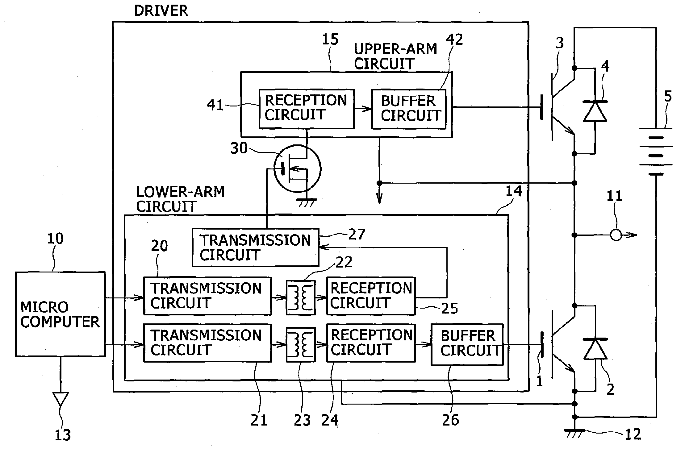
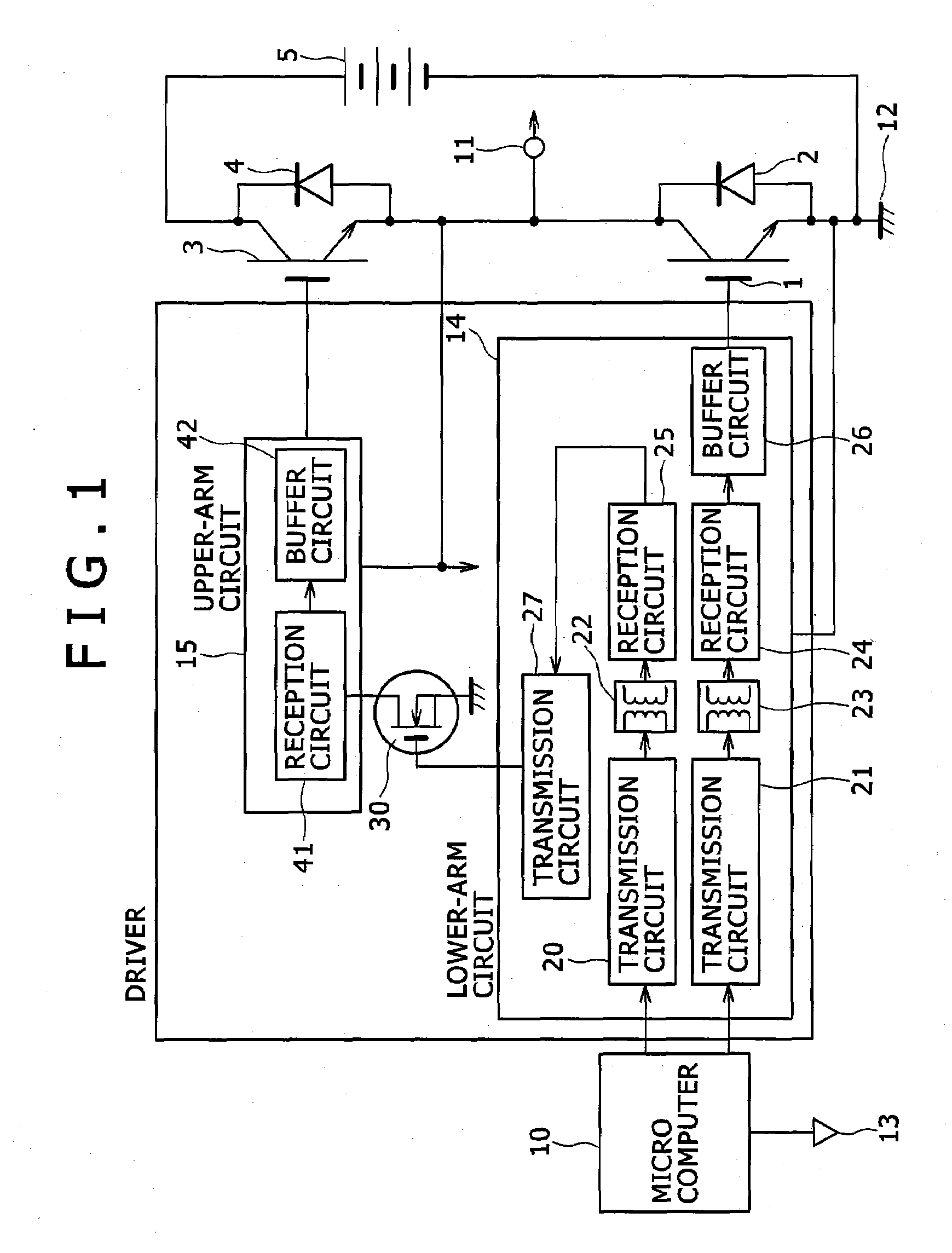
[0029]FIG. 1 is a circuit block diagram of an electric power conversion apparatus being one embodiment of the present invention.

[0030]A diode 2 is connected in parallel to a lower arm IGBT 1. A diode 4 is connected in parallel to an upper IGBT 3. The emitter of the upper arm IGBT 3 is connected to the collector of the lower arm IGBT 1. The center junction between the emitter and the collector as an output 11 is connected to the connection terminal of a motor (not shown). A micro-computer ground 13 of a micro computer 10 and a ground 12 of a high voltage power supply 5 are insulated. A lower-arm driving signal from the microcomputer 10 is modulated by a transmission circuit 21 of a lower-arm circuit 14 of a driver, passed through a pulse transformer 23, demodulated by a reception circuit 24, amplified by a buffer circuit 26 and caused to turn on and off the lower arm IGBT 1. An upper-arm driving signal from the microcomputer 10 is modulated by a transmission circuit 20, passed throug...

second embodiment

[0039]FIG. 4 is a circuit diagram of an electric power conversion apparatus being another embodiment of the present invention. The present embodiment is the same as the above embodiment except the following description.

[0040]The present embodiment provides a transmission and a reception circuit for transmitting a signal from the micro computer using the pulse transformer. Although the two pulse transformers are used in the first embodiment, one pulse transformer is used in the present embodiment. The drain of the nMOSFET 52 is connected to the primary side of the pulse transformer 23 and the source thereof is connected to the micro-computer ground. One terminal of the primary side of the pulse transformer 23 is connected to high voltage side of the power supply 50. A micro-computer signal is inputted to the gate of the nMOSFET 52 through the buffer 51. A reference power supply 62 is inserted between the secondary side of the pulse transformer 23 and the lower-arm ground. The resisto...

third embodiment

[0042]FIG. 5 is a circuit diagram of an electric power conversion apparatus being another embodiment of the present invention. The present embodiment is the same as the above embodiment except the following description.

[0043]The present embodiment provides a transmission and a reception circuit for transmitting a signal from the micro computer using the pulse transformer. The drain of the nMOSFET 52 is connected to the primary side of the pulse transformer 23 and the source thereof is connected to the micro-computer ground. One terminal of the primary side of the pulse transformer 23 is connected to high voltage side of the power supply 50. An AND of the micro-computer signal and the output of an oscillation circuit 71 is inputted to the gate of the nMOSFET 52. The resistor 53 is connected to both ends of the secondary side of the pulse transformer 23. One terminal of the resistor is connected to the comparator 55. One terminal of the comparator 55 is connected to the reference elec...


PUM


Abstract

In an electric power conversion apparatus, there is reduced deterioration in insulation of a means which is provided inside an IC chip and transmits a signal from a low electric potential system to a high electric potential system. The electric power conversion apparatus includes a lower-arm circuit 14 which transmits control signals from a micro computer 10 through the pulse transformers 22 and 23 provided inside an IC chip and outputs the control signal transmitted through the pulse transformer 23 to a lower-arm IGBT 1, a high-voltage nMOS 30 which converts the electric potential of the control signal for an upper-arm IGBT 3 transmitted through the pulse transformer 22 of the lower-arm circuit 14 and an upper-arm circuit 15 which outputs the control signal of which the electric potential is converted by the high-voltage nMOS 30 to the upper-arm IGBT 3.

Description

BACKGROUND OF THE INVENTION[0001]1. Field of the Invention[0002]The present invention relates to an electric power conversion apparatus.[0003]2. Description of the Related Art[0004]It is prevalent to control a motor by an electric power conversion apparatus using a switching element. In general, the emitter of an arm switching element configuring an electric power conversion is connected to the output of the electric power conversion apparatus, so that the arm switching element is driven in an electric-potentially floating state with respect to a main power-supply earth terminal. For example, when the arm switching element is turned on, a high voltage equal to a voltage of a main power supply is applied thereto. For this reason, a signal needs transmitting from a low electric potential system in a microcomputer to a high electric potential system powered by a main power supply in order to drive the arm switching element.[0005]As a means for transmitting signals from a low electric p...

Claims


Application Information

Patent Timeline
IPC IPC(8): G05F1/66
CPCH02M7/538H03K19/017545H03K17/691H03K17/567H01L2224/48091H01L2224/49113H01L2224/48227H01L2924/13055H01L2924/13091H01L2924/00014H01L2924/00
Inventor SAKURAI, NAOKI
Owner HITACHI LTD
Why Eureka
Try Eureka