Oil cooling system, particularly for transformers feeding traction electric motors, transformer with said system and method for determining the cooling fluid flow in a cooling system

a technology of oil cooling system and transformer, which is applied in the direction of fluid pressure control, lighting and heating apparatus, instruments, etc., can solve the problems of inability to detect the flow meter, the safety monitoring of oil flowing into the cooling circuit, and the inability to ensure the safety of the cooling circuit, etc., to achieve high operating safety, easy assembly, and reliable use

Active Publication Date: 2009-09-17
ALSTOM TRANSPORT TECH SAS
View PDF10 Cites 24 Cited by
  • Summary
  • Abstract
  • Description
  • Claims
  • Application Information

AI Technical Summary

Benefits of technology

[0015]It is an aspect of the invention to provide a system of the type hereinbefore described that overcomes the drawbacks of known systems and that is relativ...

Problems solved by technology

A drawback of oil cooling systems is that the oil flowing into the cooling circuit is monitored for safety reasons.
When there is no flow or when the fluid flow is too slow, i.e. it is below a minimum threshold velocity, the paddle is not deflected and the flow meter is not able to detect the presence of the fluid flow.
Therefore, under such conditions conventional flow meters are not able to indicate the presence of a fluid flow or such indication is not reliable.
Differential pressure sensors are not very reliable, so they must be redundant, i.e. the circuit has to be provided with more than one differential pressure sensor, particularly for guaranteeing the safety levels required in the r...

Method used


Image

  • Oil cooling system, particularly for transformers feeding traction electric motors, transformer with said system and method for determining the cooling fluid flow in a cooling system
  • Oil cooling system, particularly for transformers feeding traction electric motors, transformer with said system and method for determining the cooling fluid flow in a cooling system

Examples


Embodiment Construction

[0036]Detailed descriptions of embodiments of the invention are provided herein. It should be understood, however, that the present invention may be embodied in various forms. Therefore, the specific details disclosed herein are not to be interpreted as limiting, but rather as a representative basis for teaching one skilled in the art how to employ the present invention in virtually any detailed system, structure, or manner.

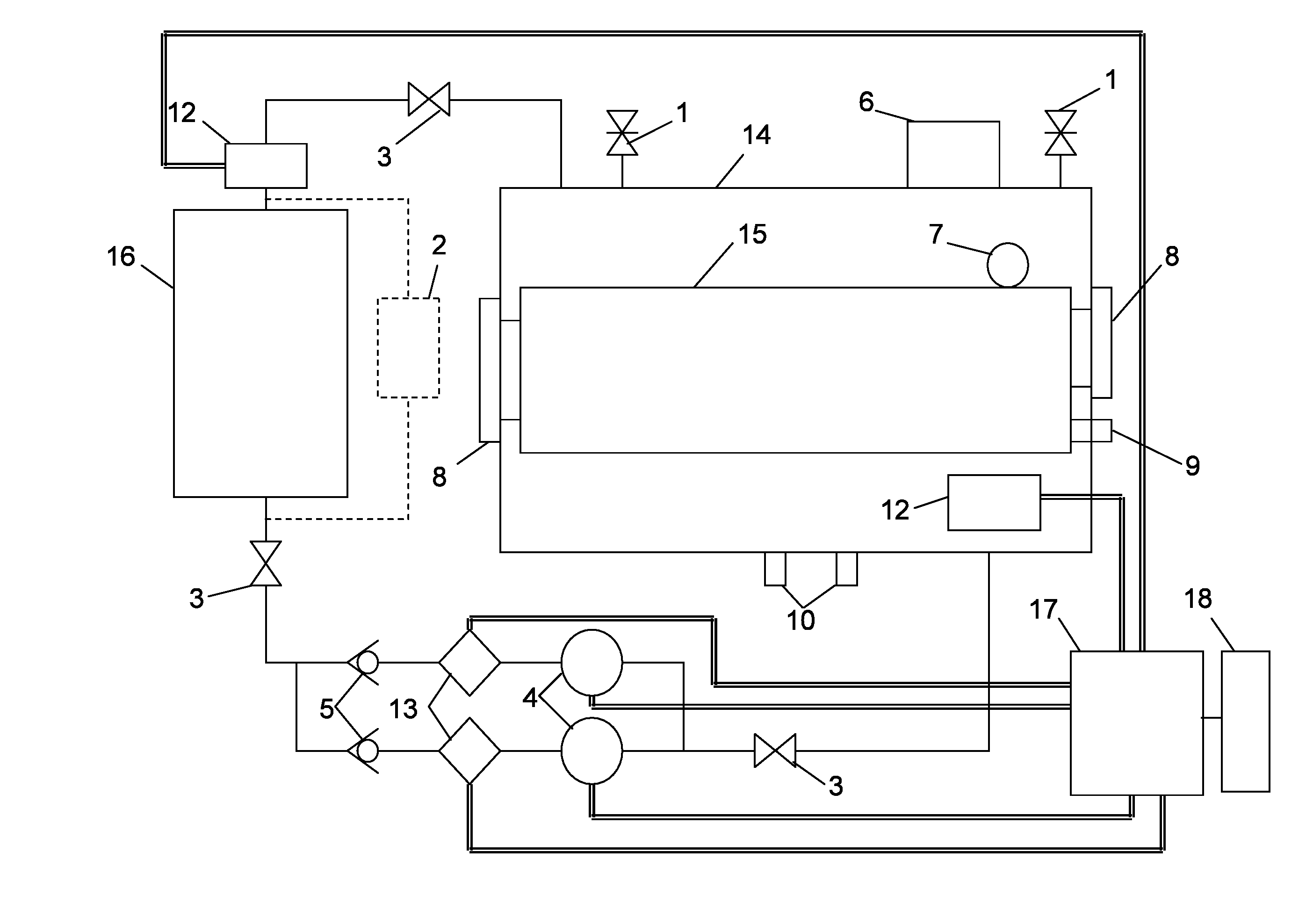
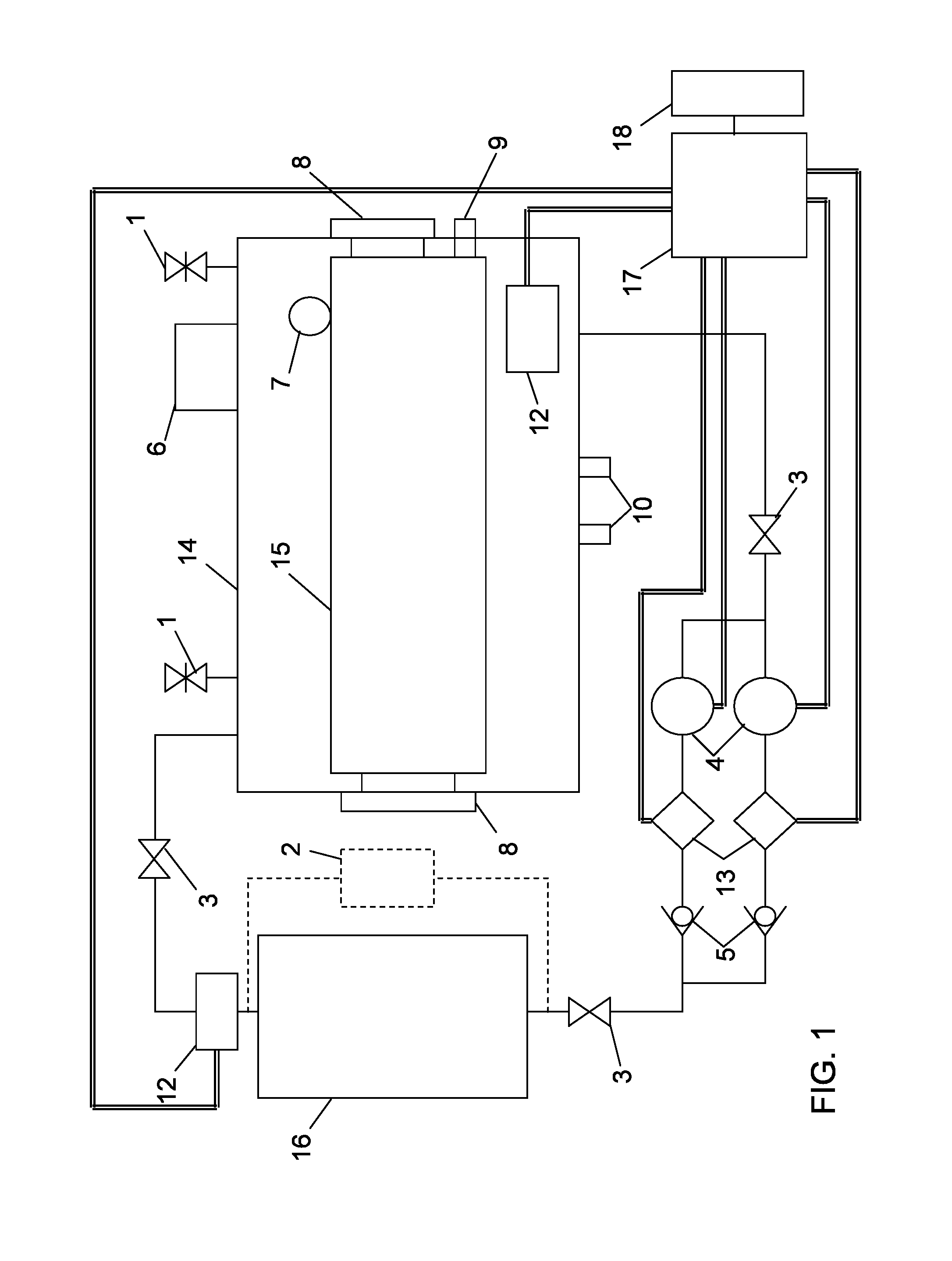
[0037]With reference to FIG. 1, there is shown a schematic block diagram of an electric transformer 15 of the type used in the railway field, for example, for feeding electric motors of electric locomotives, electric trains or the like. Transformer 15 is provided in combination with a system for cooling it, for example, with a cooling fluid having a high thermal capacity such as oil or the like.

[0038]In the illustrated block diagram, transformer 15 is not shown in details, this type of construction being known to a person skilled in the art.

[0039]Transformer 15 i...


PUM


Abstract

An oil cooling system, which may be employed for transformers feeding traction electric motors and for oil in a high viscosity condition, includes a first heat exchanger between a heat generating source to cooling oil that is connected by delivery and return ducts to a second heat exchanger cooling the oil by transmitting the heat absorbed at the first heat exchanger to an environment having a lower temperature than the cooling oil. The oil cooling system also includes devices flowing the cooling oil from the first to the second heat exchanger and vice versa, and devices monitoring oil flow in the circuit, for example by indicating operating conditions of the cooling system and/or by performing safety operations when the heat generating source becomes overheated.

Description

FIELD OF THE INVENTION[0001]The invention relates to an oil cooling system, for example, for transformers feeding traction electric motors. A system according to the invention includes a first heat exchanger that exchanges heat between a heat generating source and a cooling oil and that is connected by a delivery duct and a return duct to a second heat exchanger, which cools the oil by transferring heat absorbed at the first heat exchanger into an environment having a lower temperature.[0002]In an embodiment of the invention, cooling oil flows from the first to the second heat exchanger and vice versa, and oil flow within the circuit that includes the first and the second heat exchangers and the delivery and return ducts is monitored, for example, through a control unit providing operating conditions of the cooling system and / or through a safety unit preventing an overheating of the heat generating source.[0003]In a preferred embodiment of the invention, the heat generating source i...

Claims


Application Information

Patent Timeline
IPC IPC(8): H01F27/08G05D23/00G05D16/00
CPCH01F27/12H01F2027/406H01F2027/404
Inventor MOIA, PIERO
Owner ALSTOM TRANSPORT TECH SAS
Why Eureka
Try Eureka