Refractive spatial heterodyne spectrometer

Inactive Publication Date: 2009-09-17
NAVY USA AS REPRESENTED BY THE SEC OF THE THE
View PDF2 Cites 14 Cited by
  • Summary
  • Abstract
  • Description
  • Claims
  • Application Information

AI Technical Summary

Benefits of technology

[0009]For moderate resolution applications, the throughput, and therefore the sensitivity, of prior SHS interferometer designs are limited by contamination from unwanted grating orders within the instrument passband. The invention avoids this limitation by employing refractive prisms in lieu of diffraction gratings since refractive prisms do not produce multiple orders. As a result the refractive SHS can achieve larger throughput and a larger spectral

Problems solved by technology

For moderate resolution applications, the throughput, and therefore the sensitivity, of prior SHS interfe

Method used


Image

  • Refractive spatial heterodyne spectrometer
  • Refractive spatial heterodyne spectrometer
  • Refractive spatial heterodyne spectrometer

Examples


Embodiment Construction

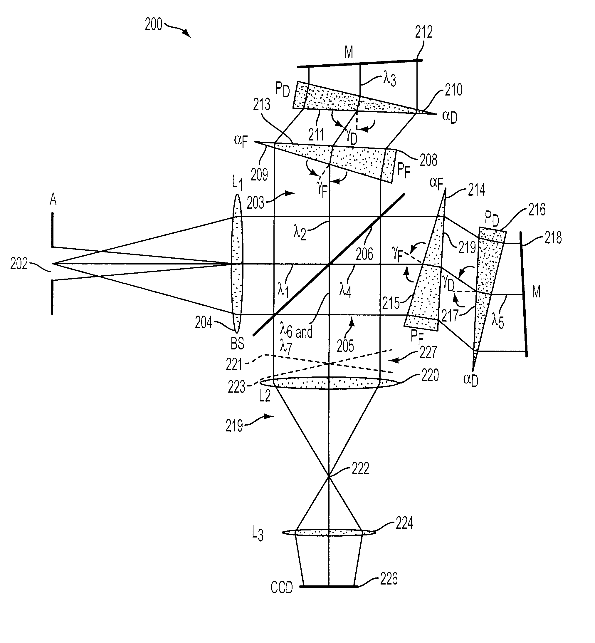
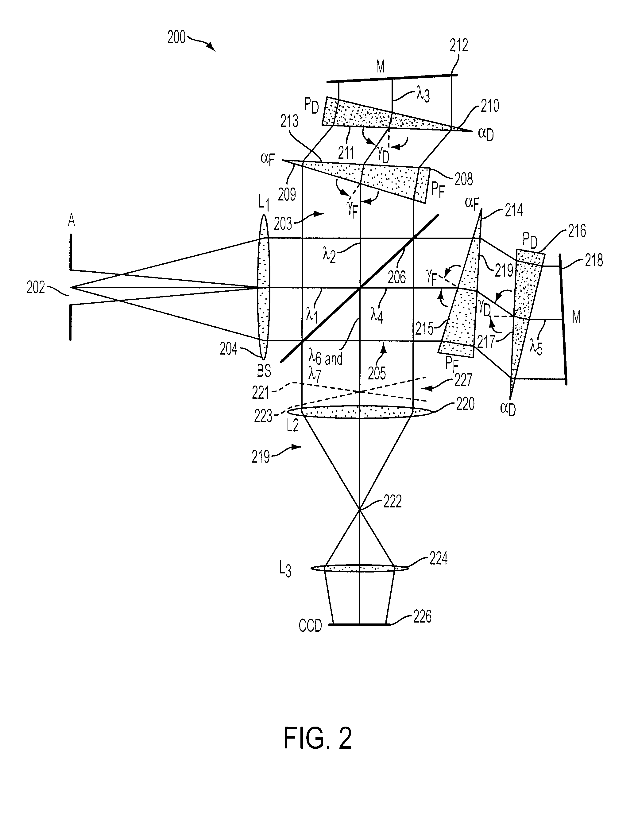
[0013]Definitions: As used herein, the term “field-widening prism” means a wedged, refractive elements whose purpose is to increase the throughput of the system by reducing the path difference change between on and off-axis rays. Exemplary field-widening prisms include prisms typically manufactured from low-dispersion glass. As used herein, the term “dispersing prism” means a wedged, refractive element whose purpose is to make the angle of deviation of the beam a function of wavelength. Exemplary dispersing prisms include prisms typically manufactured from a high-dispersion glass.

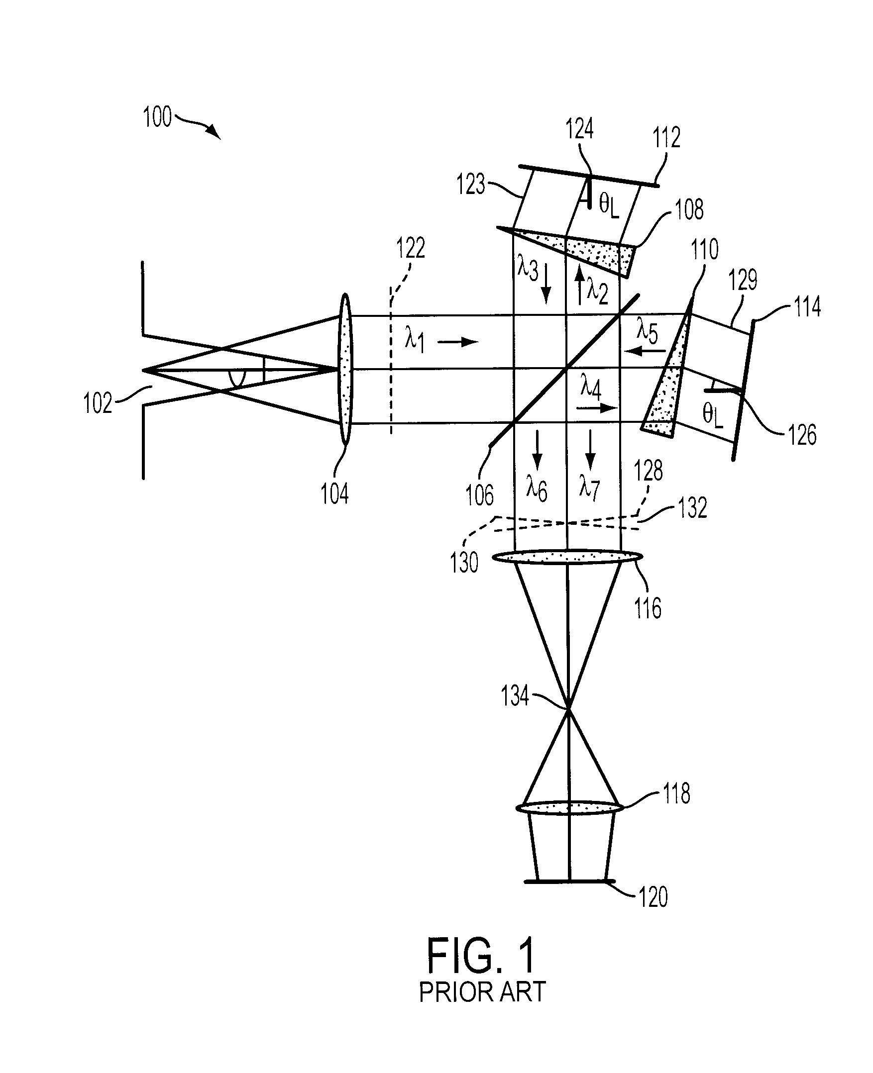
[0014]The invention is similar to the conventional SHS shown in FIG. 1 except that the diffraction gratings in each arm are replaced by a mirror and a dispersing prism. Additionally in order to obtain a large interferometer field of view a second low-dispersion field widening prism is preferably inserted in each arm. The combination of two prisms in each arm results in a system that has no contamination fro...


PUM


Abstract

A refractive spatial heterodyne spectrometer includes an input aperture for receiving an input light; a collimating lens for collimating the input light into a collimated lightbeam; and a beamsplitter for reflecting one part of the collimated light into a first arm and transmitting another part of the collimated light into a second arm. The first arm includes a first dispersing prism for receiving and refracting the first part of the collimated light, and a first mirror positioned to reflect the refracted first collimated light back through the first dispersing prism and to the beamsplitter as a first light wavefront. The second arm includes a second dispersing prism for receiving and refracting the other part of the collimated light, and a second mirror positioned to reflect this refracted light back through the second dispersing prism and to the beamsplitter as a second light wavefront. The beamsplitter transmits a portion of the first light wavefront and reflects a portion of the second light wavefront into an output optics section to inferometrically combine into an interference image, and a detector receives the interference image and outputs an interference image pattern.

Description

BACKGROUND OF THE INVENTION[0001]The present invention is directed to a spatial heterodyne spectrometer. More particularly, the invention is directed to a refractive spatial heterodyne spectrometer that employs a mirror and a dispersing prism in lieu of a diffraction grating in each arm.[0002]Passive remote sensing is increasingly useful in myriad applications, including industrial, scientific, and military. Military applications include intelligence gathering, e.g. monitoring exhaust fumes to infer the nature and scope of industrial processes , tactical battlefield applications such as chemical threat identification, and tagging, tracking, and location efforts.[0003]Spatial heterodyne spectroscopy (SHS), e.g. as described in U.S. Pat. No. 5,059,027, Roesler et al., issued Oct. 22, 1991, and incorporated herein by reference, has primarily been used for ultraviolet applications that require very high spectral resolution and a narrow passband. Recently, SHS has also been considered fo...

Claims


Application Information

Patent Timeline
IPC IPC(8): G01J3/45
CPCG01J3/14G01J3/4532G01J3/4531
Inventor HARLANDER, JOHN M.ENGLERT, CHRISTOPH R.
Owner NAVY USA AS REPRESENTED BY THE SEC OF THE THE
Why Eureka
Try Eureka