Light-Emitting-Diode Backlight Device

Inactive Publication Date: 2009-09-17
SONY CORP
View PDF11 Cites 9 Cited by
  • Summary
  • Abstract
  • Description
  • Claims
  • Application Information

AI Technical Summary

Benefits of technology

[0013]In the LED backlight device, for achieving uniform color reproducibility over an entire screen, the color temperature of the many LEDs needs to be uniform overall. In the related LED backlight device, heat is efficiently dissipated directly from the areas where the LEDs (serving as heat-generating sources) are mounted, to restrict an overall temperature rise. In addition, in the LED backlight device, it is possible to make the temperature distribution uniform over the entire LED backlight device by reducing differences between the temperature distribution at the central area and the temperature distribution at the peripheral areas.
[0014]Accordingly, it is desirable to provide an LED backlight device which is reduced in cost and which can achieve uniform color reproducibility over an entire screen, by efficiently dissipating heat in accordance with temperature distribution variations using a simple heat dissipation structure.
[0015]According to an embodiment of the present invention, there is provided a light-emitting-diode backlight device including a light source substrate to which many light-emitting diodes are mounted, and a bottom chassis having the light source substrate mounted to a principal surface side of the bottom chassis. Illumination light emitted from each of the light-emitting diodes at the light source substrate is supplied to a display panel unit. In the light-emitting diode backlight device, a back-surface side of the bottom chassis is provided with heat-dissipating means which makes uniform a temperature distribution over the entire bottom chassis. In addition, in the light-emitting-diode backlight device, the heat-dissipating means includes a mounting plate, a heat pipe, and a radiating fin, the mounting plate being mounted to at least, for example, a central area corresponding to a high-temperature area of the bottom chassis, the heat pipe being disposed on both the high-temperature area and, for example, a peripheral area corresponding to a low-temperature area of the bottom chassis and being mounted to the mounting plate, the radiating fin being mounted to the low-temperature area and being connected to an end o

Problems solved by technology

In addition, in each of the heat-dissipating devices of the previous applications, many relatively expensive heat pipes, and a heat sink and a cooling fan, which are large, heavy, and expensive, are provided.
Therefore, costs, size, and weight are increased.
The results have made us focus attention on the fact that, regardless of the size, a particular portion of a bottom chassis (that is, a slightly upward portion of a central area of the bottom chassis) becomes a hi

Method used


Image

  • Light-Emitting-Diode Backlight Device
  • Light-Emitting-Diode Backlight Device
  • Light-Emitting-Diode Backlight Device

Examples


Example

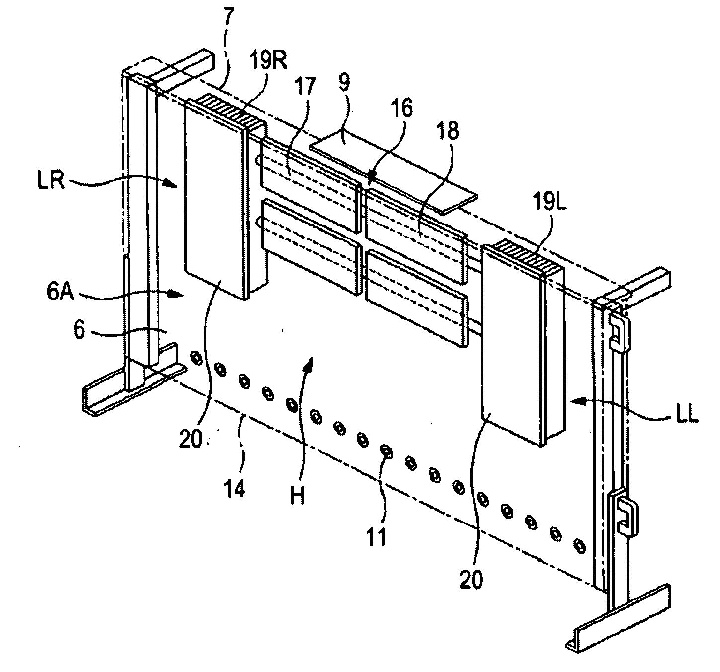
[0062]In FIG. 7, in a heat-dissipating unit 40 according to a second embodiment of the present invention, for example, two heat pipes 41U and 41L are used, and are mounted to mounting plates 42U and 42L by mounting brackets 43, respectively. Radiating fins 45L and 45R (hereunder simply referred to as the “radiating fins 45”) are disposed at the heat pipes 41U and 41L on respective sides of a central area H of a bottom chassis 7. The two heat pipes 41U and 41L have lengths extending towards a left peripheral area LL and a right peripheral area LR. Since, in the heat-dissipating unit 40, these structural members are equivalent to the structural members of the above-described heat-dissipating units 16, they will not be described in detail below.

[0063]The mounting plate 42U of the heat-dissipating unit 40 is formed with a horizontally long rectangular shape that is slightly longer than the heat pipe 41U, and has fin mounting portions 42U1 and 42U2 at respective ends thereof. The mountin...

Example

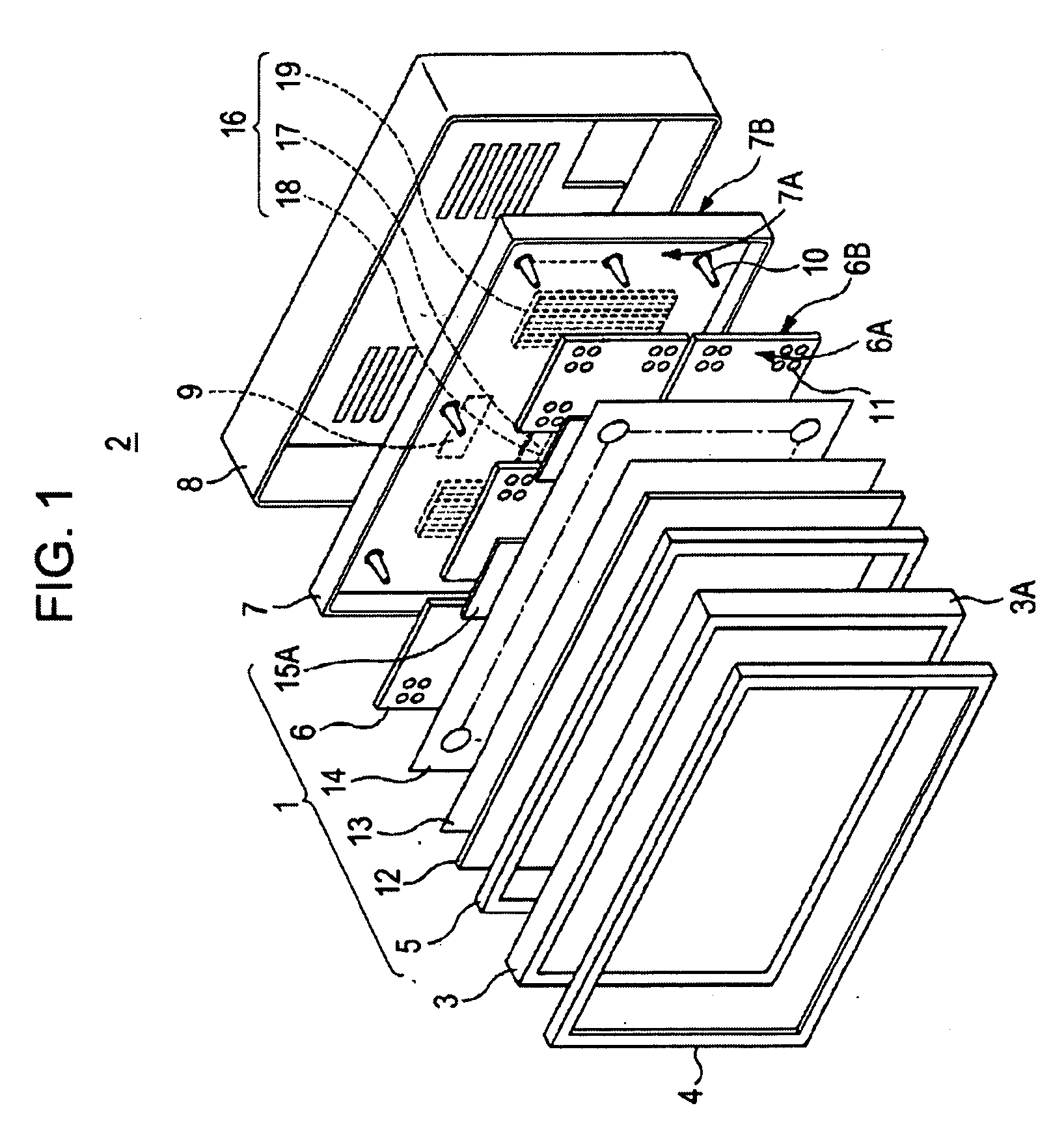
[0066]In FIG. 8, a heat-dissipating unit 50 according to a third embodiment of the present invention is applied to, for example, a liquid crystal display device in which a driving control unit 9 is disposed so as to oppose a portion along a lower edge of a central portion near an electrode draw-out area of a liquid crystal panel unit 3. In the liquid crystal display device, as mentioned above, a large amount of heat is generated from each LED 11, electronic components, of circuit boards 15, etc., as well as the high-performance driving control unit 9. In the liquid crystal display device, the temperature of a central area H of a bottom chassis 7 becomes even higher when heat generated from the driving control unit 9 is directly radiated. In the liquid crystal display device, the heat-dissipating unit 50 efficiently dissipates heat at the central area H of the bottom chassis 7 to make uniform the temperature distribution over the entire bottom chassis 7.

[0067]In the liquid crystal di...


PUM


Abstract

A light-emitting-diode backlight device includes a light source substrate to which many light-emitting diodes are mounted, and a bottom chassis having the light source substrate mounted to a principal surface side of the bottom chassis. Illumination light from the light-emitting diodes is supplied to a display panel unit. A back-surface side of the bottom chassis is provided with a heat-dissipating unit making uniform a temperature distribution over the entire bottom chassis. The heat-dissipating unit includes a mounting plate, a heat pipe, and a radiating fin. The mounting plate is mounted to at least a high-temperature area of the bottom chassis. The heat pipe is disposed on both the high-temperature area and a low-temperature area, and is mounted to the mounting plate. The radiating fin is mounted to the low-temperature area, and connected to an end of the heat pipe.

Description

CROSS REFERENCES TO RELATED APPLICATIONS[0001]The present invention contains subject matter related to Japanese Patent Application JP 2008-064450 filed in the Japanese Patent Office on Mar. 13, 2008, the entire contents of which are incorporated herein by reference.BACKGROUND OF THE INVENTION[0002]1. Field of the Invention[0003]The present invention relates to an LED backlight device in which a many light emitting diodes (LEDs) serve as light sources.[0004]2. Description of the Related Art[0005]An LED backlight device is, for example, assembled to a display panel (such as a liquid display panel), and illumination light emitted from each LED is supplied to a display panel unit, to form a display device. Compared to, for example, a cold cathode fluorescent lamp (CCFL), which is generally used as a light source in a related art, the LED backlight device is provided with many LEDs which are low in cost and which have various characteristics, such as being small in size / being light, havi...

Claims


Application Information

Patent Timeline
IPC IPC(8): F21V7/04
CPCG02F1/133603G02F2001/133628H01L2924/0002H01L2924/00H05K7/2099G02F1/133628G02F1/1335G02F1/1333
Inventor SHIBATA, HIROKAZUSUZUKI, YUICHI
Owner SONY CORP
Why Eureka
Try Eureka