Identifying device by biometrics information

a biometric and information technology, applied in the field of personal identification identification devices, can solve the problems of affecting the reliability of the system, and high plagiarism risk of password or id cards

Inactive Publication Date: 2009-09-17
FUJITSU LTD
View PDF15 Cites 113 Cited by
  • Summary
  • Abstract
  • Description
  • Claims
  • Application Information

AI Technical Summary

Benefits of technology

[0032](7) The living-body detecting means detects an electric resistance value of the finger and di

Problems solved by technology

However, the password or ID card has a high risk of plagiarism, and realization of more reliable personal identification (identification that a user of equipment is the user himself/herself registered in advance) is in a strong demand.
In a personal identification system using a fingerprint as above, illegal use using a forged fingerprint has been pointed out as one of problems in realizing more reliable personal identification.
And the illegal use by impersonation might undermine reliability of the system.
When silicon or rubber is used as a material for the artificial finger, since these materials do not conduct electricity and a capacitance type fingerprint sensor does not have a function to sample a fingerprint image from an artificial finger made of silicon or an artificial finger made of rubber, the above illegal use can not be committed.
However, it is pointed out that, if gummy substance (s

Method used


Image

  • Identifying device by biometrics information
  • Identifying device by biometrics information
  • Identifying device by biometrics information

Examples


first embodiment

[2-1] First Embodiment

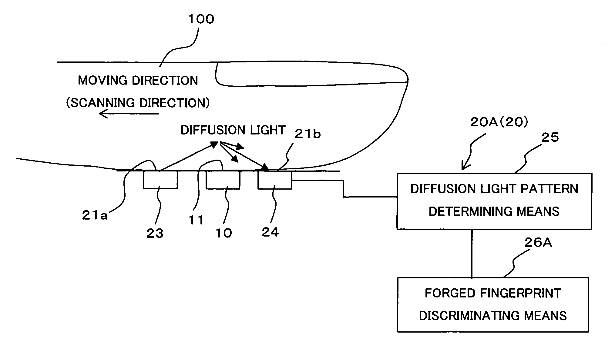
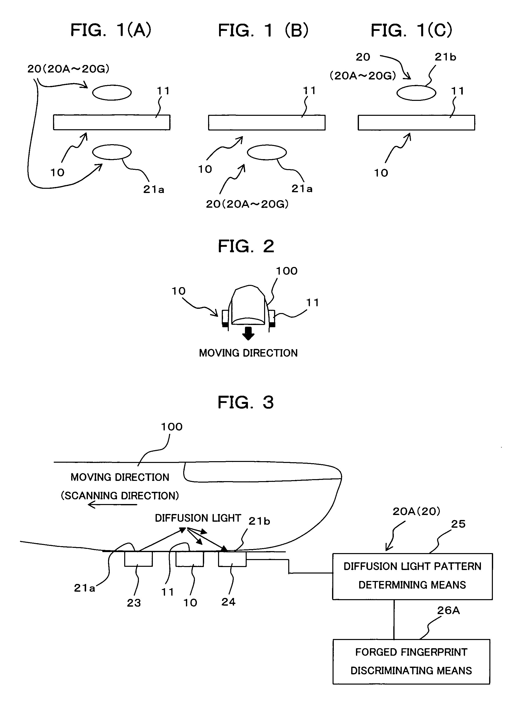
[0074]FIG. 3 is a block diagram showing a construction of the identifying device (living-body detecting means) by biometrics information as the first embodiment of the present invention. The identifying device of the first embodiment shown in FIG. 3 is provided with a living-body detecting means (living-body detecting sensor) 20A comprised by a light emitting section 23, a light receiving section 24, a diffusion-light pattern determining means 25 and a forged fingerprint discriminating means 26A.

[0075]The light emitting section 23 emits and irradiates light of a specific wavelength to the finger 100, for which the fingerprint image is being sampled, and its light emitting surface is arranged in contact with the finger 100 being moved on the side of the finger moving direction (left side in this figure) of the sampling surface 11 as the living-body detection surface 21a and flush with or substantially flush with the sampling surface 11.

[0076]The light receiving ...

third embodiment

[2-3] Third Embodiment

[0098]FIG. 6 is a block diagram showing a construction of the identifying device (living-body detecting means) by biometrics information as the third embodiment of the present invention. The identifying device of the third embodiment shown in FIG. 6 is provided with a living-body detecting means (living-body detecting sensor) 20C comprised by a pair of electrodes 28a, 28b, a resistance value determining means 29 and a forged fingerprint discriminating means 26C.

[0099]The pair of electrodes 28a, 28b receives an electric power of a predetermined voltage from a power source, not shown, and flows an electric current through the finger 100, for which the fingerprint image is being sampled, from the electrode 28a to the electrode 28b. Exposed surfaces of the electrodes 28a, 28b are arranged as the living-body detection surface 21b to be in contact with the finger 100 being moved on the side (right side in the figure) opposite to the finger moving direction of the sam...

fourth embodiment

[2-4] Fourth Embodiment

[0102]FIG. 7 is a block diagram showing a construction of the identifying device (living-body detecting means) by biometrics information as the fourth embodiment of the present invention, and FIG. 8 is a view showing an example of the fingerprint image with noise sampled in the fourth embodiment.

[0103]The identifying device in the fourth embodiment shown in FIG. 7 is provided with a living-body detecting means (living-body detecting sensor) 20D comprised by an electrode 30, a pulse signal generating means 31, an image noise detecting means 32 and a forged fingerprint discriminating means 26D. This living-body detecting means 20D applies an electric noise of a specific pattern to the finger 100 and discriminates a living body from a forged fingerprint based on appearance situation of a noise on the fingerprint image sampled by the fingerprint sensor 10.

[0104]Here, the sweep type fingerprint sensor 10 is a capacitance type or an electric-field detection type (we...


PUM


Abstract

In an identifying device for performing personal identification using biometrics information such as an iris, face, blood vessel pattern, auricle, fingerprint, palm print, hand print or the like, in order to surely discriminate a living body from a non-living body and to surely preclude illegal use by impersonation using a forged fingerprint or the like, a biometrics information input section samples/inputs biometrics information for verification as image information from a living body portion relatively moving with respect to this biometrics information input section, and living-body detection surfaces in a living-body detecting means is arranged in contact with or in the proximity to the living body portion being moved with respect to the biometrics information input section so as to input the biometrics information for verification.

Description

TECHNICAL FIELD[0001]The present invention relates to an identifying device for personal identification using biometrics information such as iris, face, blood vessel pattern, auricle, fingerprint, palm print or hand print, for example, and particularly to an identifying device having a living-body detecting function for detecting if a living body portion, for which the biometrics information is to be sampled, is a living body or not at sampling of the biometrics information from the living body portion of a person to be identified.BACKGROUND ART[0002]Small-sized information equipment including a cellular phone and a Personal Digital Assistant (PDA) has become capable of connection to a network and storage of a large amount of personal information with recent sophistication of functions, and a demand for improvement of security function in such equipment is extremely high.[0003]In order to ensure security in such equipment, personal identification using a password or ID (IDentifiacto...

Claims


Application Information

Patent Timeline
IPC IPC(8): G06K9/00A61B5/117G06T1/00
CPCG06K9/0012G06V40/1394
Inventor SHINZAKI, TAKASHI
Owner FUJITSU LTD
Why Eureka
Try Eureka