Control device and control method for spark-ignition direct-injection internal combustion engine

a technology of control device and internal combustion engine, which is applied in the direction of electrical control, process and machine control, etc., can solve the problems of insufficient total fuel injection amount and lean air-fuel mixture in the combustion chamber, and achieve the effects of stabilizing combustion, reducing injection amount, and improving combustion sta

Inactive Publication Date: 2009-09-17
TOYOTA JIDOSHA KK +1
View PDF3 Cites 7 Cited by
  • Summary
  • Abstract
  • Description
  • Claims
  • Application Information

AI Technical Summary

Benefits of technology

[0010]According to the present invention, two-split injection logic is adopted in some cases, for example, in the direct-injection gasoline engine, in order to reduce an injection amount and stabilize combustion by improving a mixing state of the air-fuel mixture (air and fuel) by injecting fuel in two-split injection (particularly in the cold state where a combustion state is not preferable). If the second fuel injection is started before the first fuel injection of the two-split injection logic ends (before fuel in an amount required in the first injection is injected), however, the total fuel injection amount is insufficient and the air-fuel mixture in the combustion chamber becomes lean. Accordingly, in such a case, the two-split injection logic is changed to the single injection logic, so that satisfactory air-fuel ratio can be maintained. As the two-split injection logic is adopted otherwise, the combustion state can be improved particularly in the cold state. Consequently, a control device of a spark-ignition direct-injection internal combustion engine realizing a satisfactory injection state when fuel is injected in two-split injection in the fuel injection process can be provided.
[0018]According to the present invention, the two-split injection logic is adopted in some cases in the direct-injection gasoline engine, in order to reduce an injection amount and stabilize combustion by improving a mixing state of the air-fuel mixture (air and fuel) by injecting fuel in two-split injection (particularly in the cold state where a combustion state is not preferable). If the second fuel injection is started before the first fuel injection of the two-split injection logic ends (before fuel in an amount required in the first injection is injected), however, the total fuel injection amount is insufficient and the air-fuel mixture in the combustion chamber becomes lean. Accordingly, in such a case, shortage caused by the start of the second fuel injection while the first injection of the two-split injection logic is being performed is calculated. Such shortage is subtracted from the amount of first injection of the two-split injection logic to calculate the amount of first injection of the two-split injection logic. In addition, the shortage is added to the amount of second injection of the two-split injection logic to calculate the amount of second injection of the two-split injection logic. Thus, fuel can be injected in two-split injection, without shortage in the total fuel injection amount being caused. Accordingly, the combustion state can be improved particularly in the cold state. Consequently, a control device of a spark-ignition direct-injection internal combustion engine realizing a satisfactory injection state when fuel is injected in two-split injection in the fuel injection process can be provided.

Problems solved by technology

If the second fuel injection is started before the first fuel injection of the two-split injection logic ends (before fuel in an amount required in the first injection is injected), however, the total fuel injection amount is insufficient and the air-fuel mixture in the combustion chamber becomes lean.

Method used


Image

  • Control device and control method for spark-ignition direct-injection internal combustion engine
  • Control device and control method for spark-ignition direct-injection internal combustion engine
  • Control device and control method for spark-ignition direct-injection internal combustion engine

Examples


first embodiment

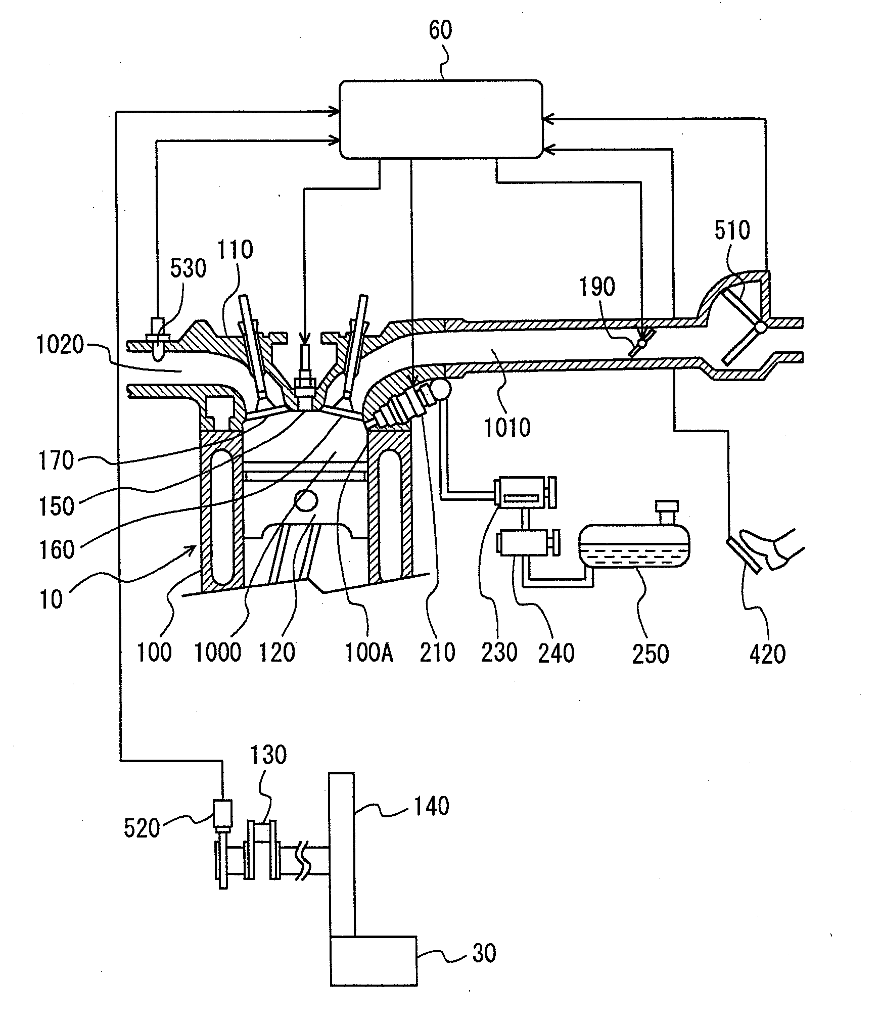
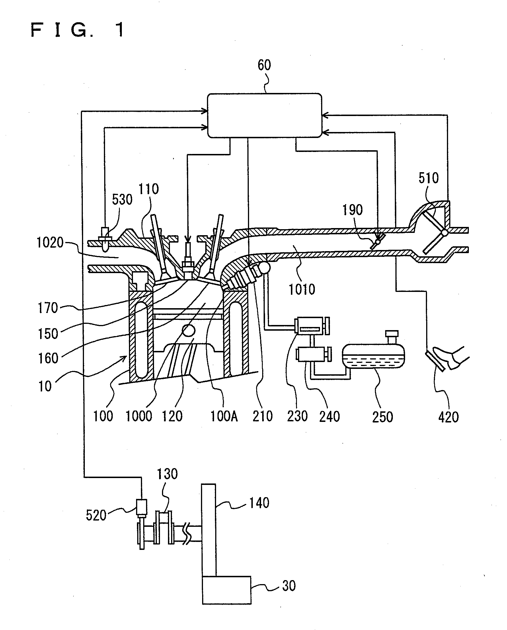
[0028]FIG. 1 shows an overall configuration diagram of a direct-injection engine controlled by an engine control device according to the present embodiment.

[0029]In an engine 10, a cylinder head 110 is attached above a cylinder block 100 in a manner covering the same, and a piston 120 is slidably held within a cylinder 100A formed in cylinder block 100. Vertical reciprocating motion of piston 120 within cylinder 100A is converted to rotational movement of a crankshaft 130 and transmitted to a transmission and the like. Crankshaft 130 is connected to a starter 30 with a flywheel 140 being interposed, at the time of start of the engine.

[0030]A combustion chamber 1000 is formed above piston 120, with cylinder block 100 and cylinder head 110 forming the wall of the chamber. In combustion chamber 1000, combustion of the air-fuel mixture is conducted, and explosive force in combustion causes piston 120 to carry out vertical reciprocating motion. A spark plug 150 provided in such a manner ...

second embodiment

[0062]A second embodiment of the present invention will now be described. It is noted that description of the structure (including hardware and flowchart) the same as in the first embodiment above will not be repeated.

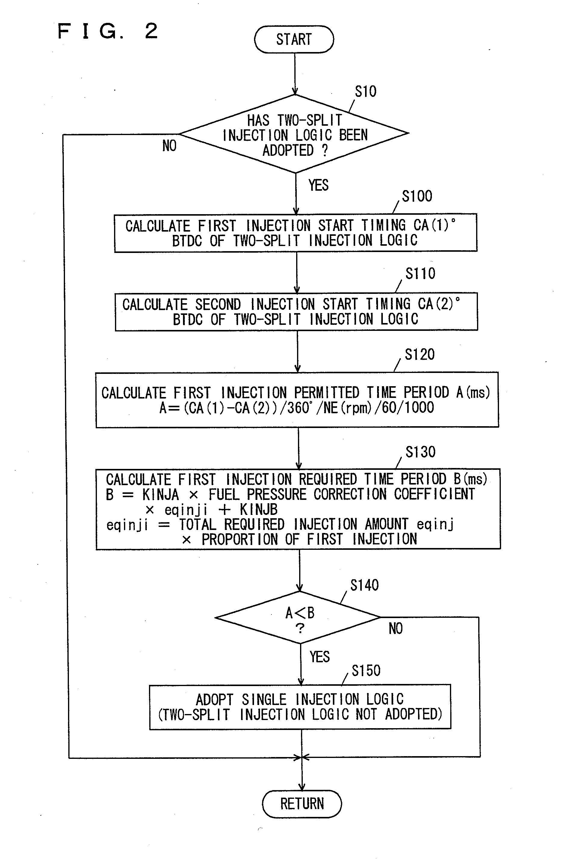
[0063]Engine ECU 60 according to the present embodiment calculates an injection upper limit time period τ (ms) representing the upper limit of the first injection permitted time period, using a map employing first injection permitted time period A calculated in the first embodiment and engine speed NE as parameters. Here, engine ECU 60 executes a program shown in a flowchart different from the flowchart shown in FIG. 2.

[0064]A control configuration of a program executed by engine ECU 60 according to the present embodiment will be described with reference to FIG. 5. It is noted that the processing in the flowchart shown in FIG. 5 the same as that in FIG. 2 is given the same step number. As the processing is the same, detailed description will not be repeated.

[0065]In S2...

third embodiment

[0069]A third embodiment of the present invention will now be described. It is noted that description of the structure (including hardware and flowchart) the same as in the first embodiment above will not be repeated.

[0070]In engine 10 controlled by engine ECU 60 according to the present embodiment, if first injection required time period B is longer than first injection permitted time period A, fuel in the entire first injection required amount cannot be injected, and shortage is caused. Accordingly, the shortage is compensated for in the second injection. Here, engine ECU 60 executes a program shown in a flowchart different from the flowchart shown in FIG. 2.

[0071]A control configuration of the program executed by engine ECU 60 according to the present embodiment will be described with reference to FIG. 7. It is noted that the processing in the flowchart shown in FIG. 7 the same as that in FIG. 2 is given the same step number. As the processing is the same, detailed description wi...


PUM


Abstract

If two-split injection logic has been adopted, an engine ECU executes a program including the steps of calculating first injection start timing of the two-split injection logic, calculating second injection start timing of the two-split injection logic, calculating a first injection permitted time period A of the two-split injection logic, calculating a first injection required time period B of the two-split injection logic, and adopting single injection logic instead of the two-split injection logic if the first injection start timing A of the two-split injection logic is shorter than the first injection required time period B of the two-split injection logic.

Description

TECHNICAL FIELD[0001]The present invention relates to a control device of an internal combustion engine in which fuel is directly injected into a cylinder, and more particularly to a control device realizing a satisfactory combustion state in such an internal combustion engine.BACKGROUND ART[0002]A direct-injection engine in which fuel is directly injected into a combustion chamber, such as a diesel engine, has been put into practical use today also in the field of a gasoline engine for running of a vehicle or the like. The gasoline engine includes an in-cylinder injector for injecting fuel into the combustion chamber and a spark plug, in which fuel is injected into a cylinder in the compression stroke to conduct semi-stratified combustion when an internal combustion engine is in a low load state such as during idling, whereas fuel is injected into the cylinder in the intake stroke to conduct homogeneous combustion when the internal combustion engine is in a high load state, thus ac...

Claims


Application Information

Patent Timeline
Patent Type & Authority Applications(United States)
IPC IPC(8): F02D41/30
CPCF02D41/26F02D41/3011Y02T10/44F02D2041/389F02D41/402Y02T10/40
Inventor HIROWATARI, SEIJITERAOKA, MASAHIKOMAEMURA, JUNFUJIKI, TOSHITAKA
Owner TOYOTA JIDOSHA KK
Why Eureka
Try Eureka