System for extending the turndown range of a turbomachine

a turbomachine and turndown range technology, applied in the direction of steam engine plants, machines/engines, mechanical apparatus, etc., can solve the problems of not being able to meet the demand in the energy market, not always feasible, and the operation of the turbomachine at partload,

Inactive Publication Date: 2009-09-24
GENERAL ELECTRIC CO
View PDF11 Cites 37 Cited by
  • Summary
  • Abstract
  • Description
  • Claims
  • Application Information

AI Technical Summary

Benefits of technology

[0006]In accordance with an embodiment of the present invention, a system for extending a turndown range of a turbomachine operating at partload, the system comprising: a turbomachine comprising a compressor, which receives an inlet-air; a combustion system; and a turbine section; wherein the turbomachine produces an exhaust-gas; a heat recovery steam generator (HRSG), wherein the HRSG receives a portion of the exhaust-gas and produces steam; and at least one air preheater comprising at least one heat exchanging section, wherein the at least one air preheater heats the inlet-air before the inlet-air flows to the compressor; wherein a portion of the at least one heat exchanging section receives a fluid at a temperature allowing for heating of the inlet-air; and wherein the fluid flows from a source external to the turbomachine; and wherein heating the inlet-air reduces an output of the turbomachine and extends the turndown range.

Problems solved by technology

However, baseload operation, though desired by operators, is not always feasible.
There may not be a demand in the energy market (electrical grid, or the like) for all of the energy generated at baseload.
A turbomachine operating at partload, may not maintain emissions compliance over the entire partload range, (from spinning reserve to near baseload).

Method used


Image

  • System for extending the turndown range of a turbomachine
  • System for extending the turndown range of a turbomachine
  • System for extending the turndown range of a turbomachine

Examples


first embodiment

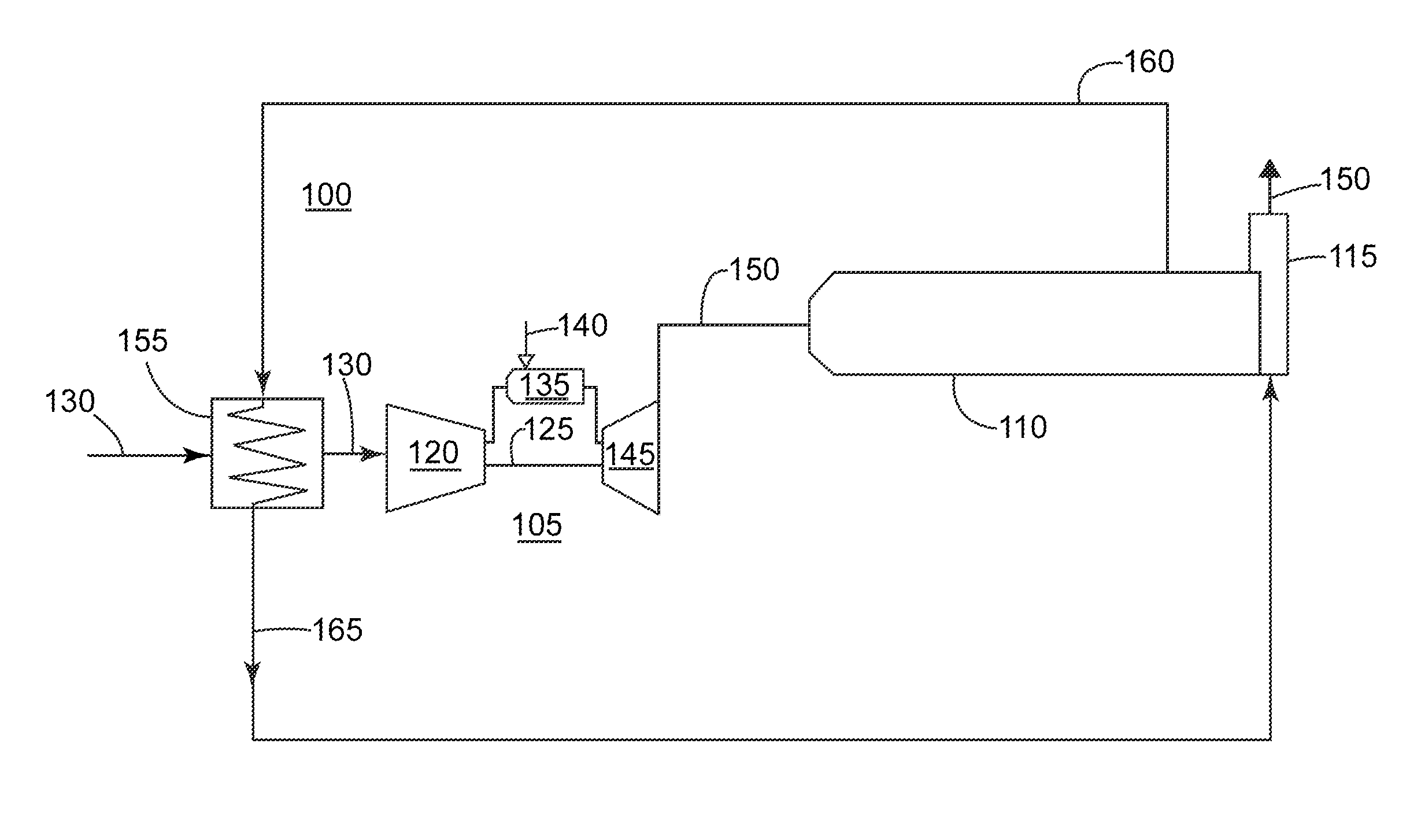
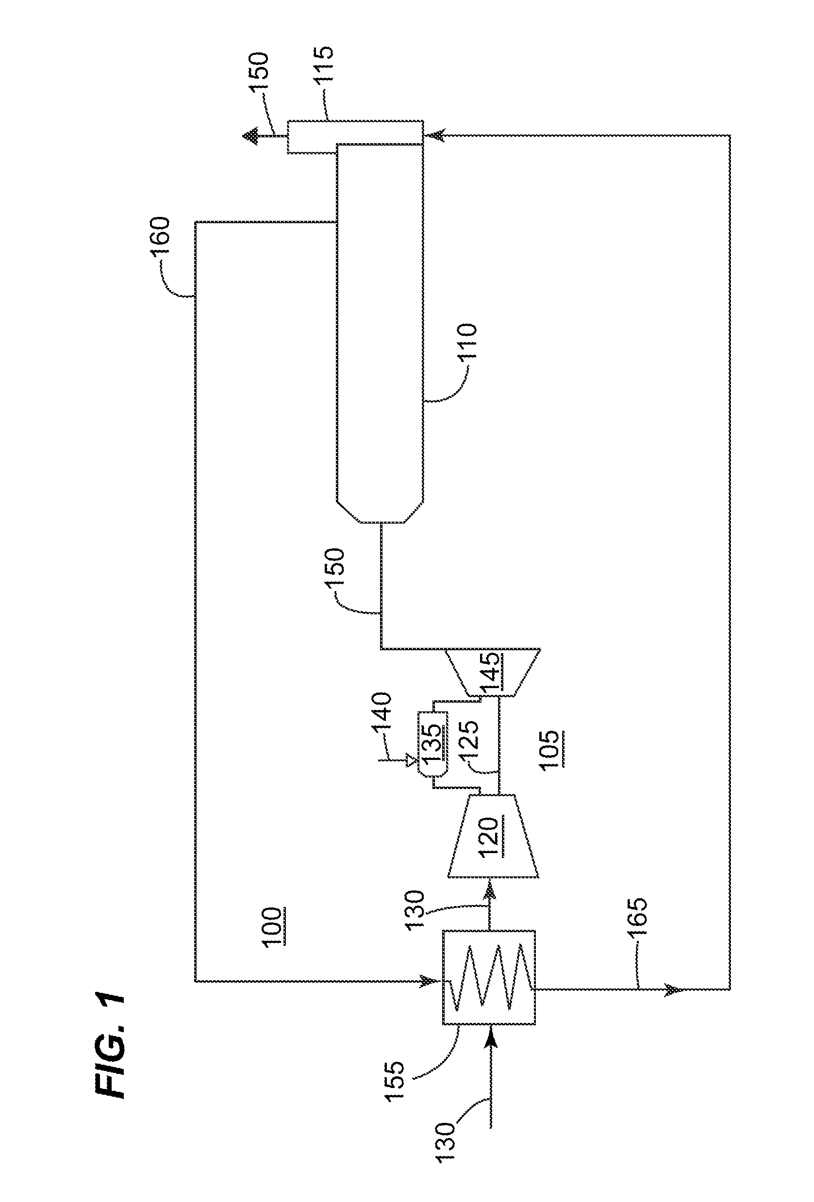
[0014]Referring now to the Figures, where the various numbers represent like elements throughout the several views, FIG. 1 is a schematic illustrating an example of a system 100 for extending the turndown range of a gas turbine 105 in accordance with the present invention.

[0015]FIG. 1 illustrates a site comprising a gas turbine 105: a heat recovery steam generator (HRSG) 110; a stack 115; and an air preheater 155. Generally, the gas turbine 105 comprises an axial flow compressor 120 having a shaft 125. Inlet-air 130 enters the compressor 120, is compressed and then discharged to a combustion system 135, where a fuel 140, Such as natural gas, is burned to provide high-energy combustion gases which drives the turbine section 145. In the turbine section 145, the energy of the hot gases is converted into work, some of which is used to drive the compressor 120 through the shaft 125, with the remainder available for useful work to drive a load such as the generator, mechanical drive, or t...

second embodiment

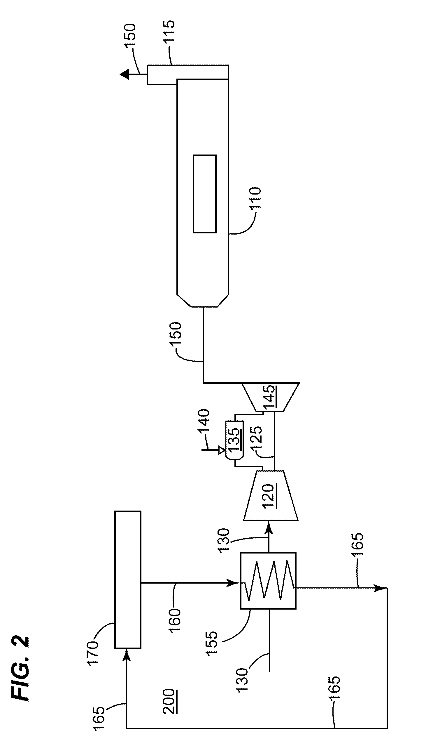
[0028]The EES 170 may provide sufficient energy to heat the inlet-air 130 to the temperature that allows for extending the turndown range. As illustrated in FIG. 2, the EES 170 may eliminate the need for extracting the exhaust-gas 150 from the HRSG 110. In this second embodiment, the exhaust-gas 150 may be used for other purposes and / or may flow through the stack 115. Alternatively, the EES 170 may operate in conjunction with the embodiment of illustrated in FIG. 1. Here, the EES 170 may operate as the primary energy system for increasing the temperature of the inlet-air 130 and the extraction from the HRSG 110, may serve as a secondary energy system (and vice-versa).

[0029]The EES 170 may include at least one of the following energy systems: a wind turbine, a boiler, an engine, an additional combustion turbine, an additional HRSG, a power plant, a solar energy source, geothermal energy source, fuel cell / chemical reaction, external process, and combinations thereof; none of which are...

third embodiment

[0033]In this third embodiment, the preheater supply line 160 may be integrated with a fuel heater supply line 180. Here, a portion of the exhaust-gas 150 may flow into the fuel heater 175. Another portion of the exhaust-gas 150 may flow into the air preheater 155. After flowing through the fuel heater 175, the exhaust-gas 150 may flow through the fuel heater discharge line 185 to the air preheater 155. After flowing to the air preheater 155, the exhaust-gas 150 may then flow through the preheater discharge line 165 to the stack 115 and / or the HRSG 110, as previously described.

[0034]FIG. 4 is a schematic illustrating an example of a system 400 for extending the turndown range of a gas turbine 105 in accordance with a fourth embodiment of the present invention. Here, the primary difference between this fourth embodiment and the first embodiment is that the exhaust-gas 150 is extracted from the stack 115, as opposed to the HRSG 110, as illustrated in FIG. 1.


PUM


Abstract

A system for heating the inlet-air of a gas turbine is provided. The system may incorporate an external energy source to increase the temperature of the inlet-air. The system may extend the turndown of a gas turbine operating at partload.

Description

BACKGROUND OF THE INVENTION[0001]The present invention relates to the operation of a turbomachine, and more particularly to a system for extending the turndown range by heating the inlet-air.[0002]Turbomachines, such as gas turbines, aero-derivatives, or the like, commonly operate in a combined-cycle and / or cogeneration mode. In combined-cycle operation, a heat recovery steam generator, which generates steam, receives the exhaust-gas from the turbomachine; the steam then flows to a steam turbine that generates additional electricity. In a co-generation operation, a portion of the steam generated by the heat recovery steam generator is sent to a separate process requiring the steam.[0003]Combined-cycle and cogeneration plants are rated to generate the maximum amount of energy (mechanical, electrical, etc) while operating at baseload. However, baseload operation, though desired by operators, is not always feasible. There may not be a demand in the energy market (electrical grid, or th...

Claims


Application Information

Patent Timeline
Patent Type & Authority Applications(United States)
IPC IPC(8): F01K23/10F02C6/04F02C7/08
CPCF02C7/047Y02E20/14F02C7/08F02C6/18
Inventor WANG, RENHUADIANTONIO, GREGORY L.CALLEROS, ERWINGLIN, TSUNGPOFISHER, WILLIAM T.
Owner GENERAL ELECTRIC CO
Why Eureka
Try Eureka