Method of Controlling Exhaust Gas Purificaiton System, and Exhaust Gas

a technology of exhaust gas purification system and purification system, which is applied in the direction of electrical control, exhaust treatment electric control, separation process, etc., can solve the problems of difficult regeneration of filters, increased exhaust pressure, and inability to perform post injection, so as to achieve efficient recovery processing of exhaust gas purification ability, efficient regeneration control of exhaust gas purifier, and rapid rise of exhaust gas temperature

Active Publication Date: 2009-09-24
ISUZU MOTORS LTD
View PDF9 Cites 28 Cited by
  • Summary
  • Abstract
  • Description
  • Claims
  • Application Information

AI Technical Summary

Benefits of technology

[0020]With these configurations, an exhaust gas purification system that can carry out the above-described method of controlling the exhaust gas purification system can be provided, and the same operation effects can be achieved.
[0021]According to the method of controlling the exhaust gas purification system and the exhaust gas purification system in the present invention, in the exhaust gas purification system provided with an exhaust gas purifier to purify components in an exhaust gas of an internal combustion engine such as a diesel engine, in an exhaust gas temperature raising control of a regeneration control to recover the purification ability of the exhaust gas purifier, an exhaust gas temperature is quickly raised by performing a post injection with a deep air-intake throttling without performing the post injection so that white smoke is not produced by the post injection when the exhaust gas temperature is low and by performing the post injection with a shallow air-intake throttling because white smoke is not produced by the post injection when the exhaust gas temperature is high. Hereby, a stable temperature control can be performed, and the regeneration control of the exhaust gas purifier can be performed efficiently.
[0022]That is, when the exhaust gas temperature is low so that the post injection cannot be performed, the exhaust gas temperature is raised quickly because the intake air is throttled further than when the post injection is possible, and a recovery processing of the purification ability of the exhaust gas purifier can be performed efficiently.

Problems solved by technology

However, in the case where the exhaust gas temperature is low, for example, in the case where a state of low exhaust gas temperature such as an idling operation, an operation at low load and low speed, etc. is continued, an oxidation reaction is not promoted because the exhaust gas temperature is low, the temperature of the catalyst is low, and the catalyst does not activate, and it then becomes difficult to regenerate a filter by oxidizing PM.
Therefore, because accumulation of PM to the filter is continued and clogging of the filter is advanced, a problem of exhaust pressure rise is caused by the clogging of the filter.
However, in order to perform regeneration of the exhaust gas purifier efficiently by raising the exhaust gas temperature as quickly as possible, it is necessary to raise the exhaust gas temperature as quickly as possible even when the exhaust gas temperature is low such that the post injection cannot be performed due to production of the white smoke.Patent Document 1: Japanese patent application Kokai publication No. 2003-83139

Method used


Image

  • Method of Controlling Exhaust Gas Purificaiton System, and Exhaust Gas
  • Method of Controlling Exhaust Gas Purificaiton System, and Exhaust Gas
  • Method of Controlling Exhaust Gas Purificaiton System, and Exhaust Gas

Examples


Embodiment Construction

[0028]Below, the method of controlling the exhaust gas purification system and the exhaust gas purification system of the embodiment according to the present invention are explained with the exhaust gas purification system provided with a continuous regeneration type DPF device configured with a combination of an oxidation catalyst and a filter with catalyst as an example and by referring to the drawings.

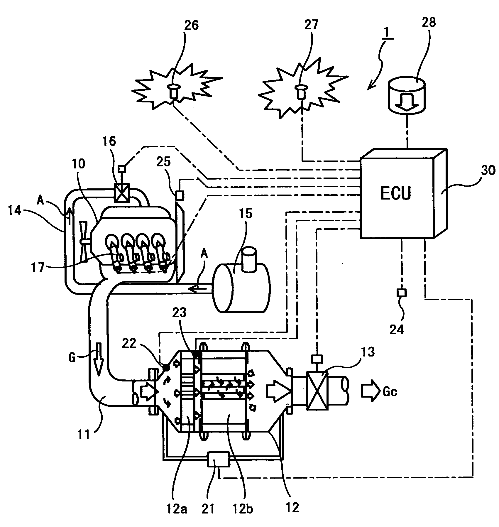
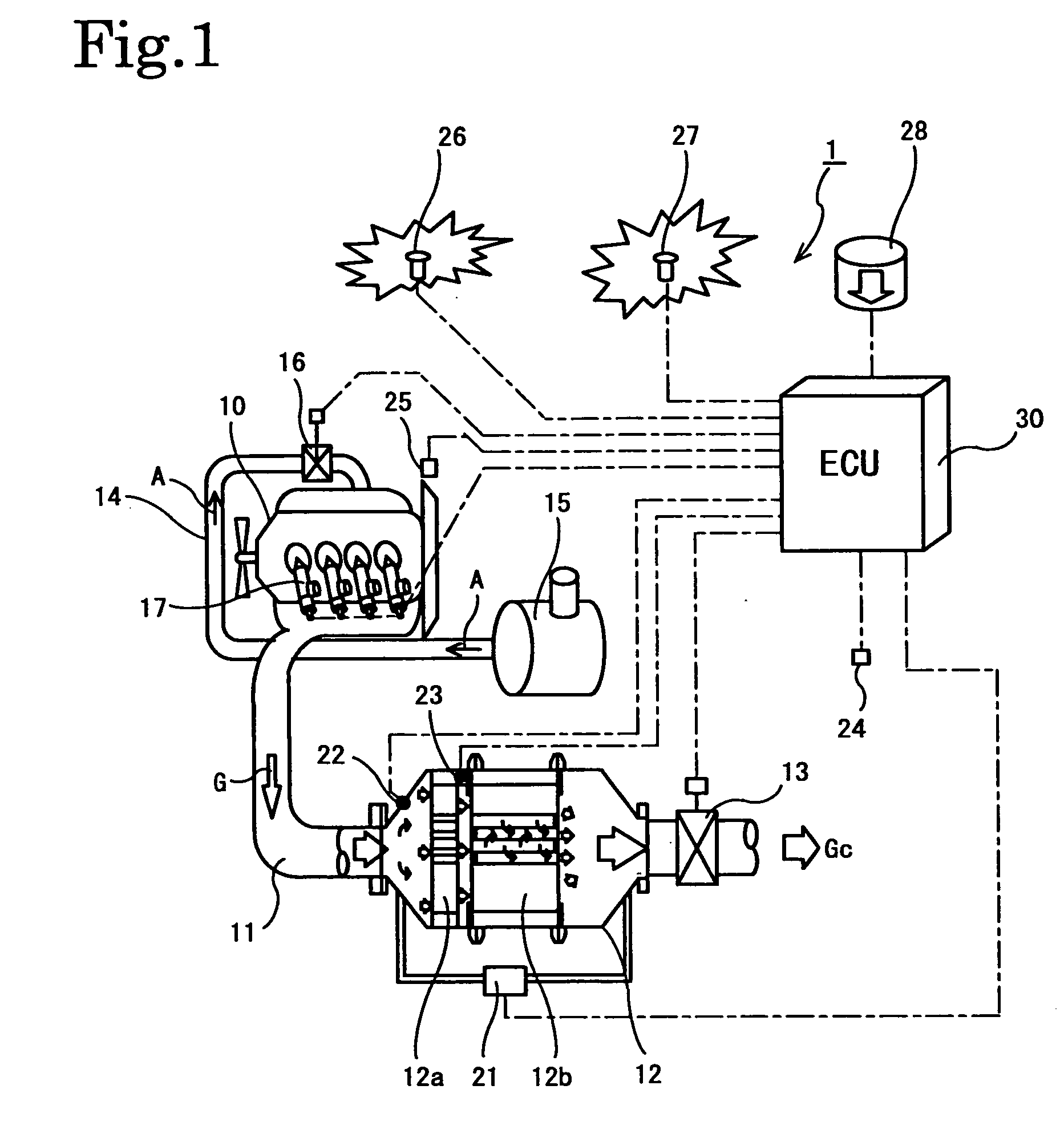
[0029]The configuration of an exhaust gas purification system 1 of this embodiment is shown in FIG. 1. This exhaust gas purification system 1 is configured to provide a continuous regeneration type DPF device 12 in an exhaust gas passage 11 of a diesel engine (an internal combustion engine) 10. This continuous regeneration type DPF device 12 is configured to have an oxidation catalyst 12a on the upstream side and a filter with catalyst 12b on the downstream side. Furthermore, an exhaust gas throttle valve (an exhaust gas throttle) 13 is provided on the downstream side of this contin...


PUM

PropertyMeasurementUnit
exhaust gas temperatureaaaaaaaaaa
temperatureaaaaaaaaaa

Abstract

In an exhaust gas temperature raising control for recovering purification ability of an exhaust gas purification device (12) of an internal combustion engine, the exhaust gas temperature is efficiently raised to a target level with white smoke prevented from being produced. To achieve this, in the exhaust gas temperature raising control in recovery control of the exhaust gas purification device (12), when the temperature (Tg1) of the exhaust gas flowing into the exhaust gas purification device (12) is lower than a predetermined judgment value (Tp), a first exhaust gas temperature raising control that does not include post injection but includes intake air restriction is performed, and when equal to or higher than the predetermined judgment value (Tp), a second exhaust gas temperature raising control that includes both the post injection and the intake air restriction is performed to set an intake air restriction amount (α) in the first exhaust gas temperature raising control greater than an intake air restriction amount (β) in the second exhaust gas temperature raising control.

Description

FIELD OF THE INVENTION[0001]The present invention relates to a method of controlling an exhaust gas purification system and an exhaust gas purification system that performs a regeneration control including both an exhaust gas temperature raising control not performing post injection and an exhaust gas temperature raising control performing post injection in order to recover the purification ability of an exhaust gas purifier to purify components in the exhaust gas of an internal combustion engine of a diesel engine, etc.DESCRIPTION OF THE RELATED ART[0002]Regulations on the exhaust amounts of particulate matter (PM: referred to as PM below) exhausted from diesel internal combustion engines as well as NOx, CO, and HC, etc. have been tightening every year. Technologies for reducing the amount of PM to be exhausted outside by collecting this PM with a filter called a diesel particulate filter (DPF: referred to as DPF below) have been developed. Among these, there are some DPF devices a...

Claims


Application Information

Patent Timeline
Patent Type & Authority Applications(United States)
IPC IPC(8): F01N9/00F01N3/023
CPCB01D53/9495Y02T10/47B01D2258/012F01N3/023F01N3/0235F01N3/035F01N3/106F01N11/002F02B2023/085F02D9/06F02D41/029F02D41/1446F02D41/405Y02T10/44B01D2251/208F02D41/024F02D41/402F02D2200/604F02D2250/38Y02T10/12Y02T10/40
Inventor WU, WEIOCHI, NAOFUMIIKEDA, SHIGERUMASHIKO, TATSUO
Owner ISUZU MOTORS LTD
Why Eureka
Try Eureka