Voltage generating circuit

a voltage generation circuit and voltage generation technology, applied in the direction of power conversion systems, dc-dc conversion, instruments, etc., can solve the problems of reduced implementation area, system influenced by forward voltage vt of diodes, and poor efficiency

Inactive Publication Date: 2009-09-24
RICOH ELECTRONIC DEVICES CO LTD
View PDF3 Cites 17 Cited by
  • Summary
  • Abstract
  • Description
  • Claims
  • Application Information

AI Technical Summary

Benefits of technology

[0049]It is a general object of the present invention to provide a charge pump...

Problems solved by technology

DC/DC converters, however, require discrete elements such as coils, which prevents the reduction of implementation area.
One disadvantage of this circuit system is said to be that the system is influenced by the forward voltage Vt of the diodes.
Thus, efficiency is very poor particularly in the case of a heavy load with a large output current (Iout).
However, the circuit according to Patent Document 1 is disadvantageous as described below with reference to FIGS. 3 and 4.
In an actual circuit operation, an in...

Method used


Image

  • Voltage generating circuit
  • Voltage generating circuit
  • Voltage generating circuit

Examples


Embodiment Construction

[0100]Embodiments of the present invention are described with reference to the drawings in which like reference numerals designate similar or identical parts throughout the views of the drawings.

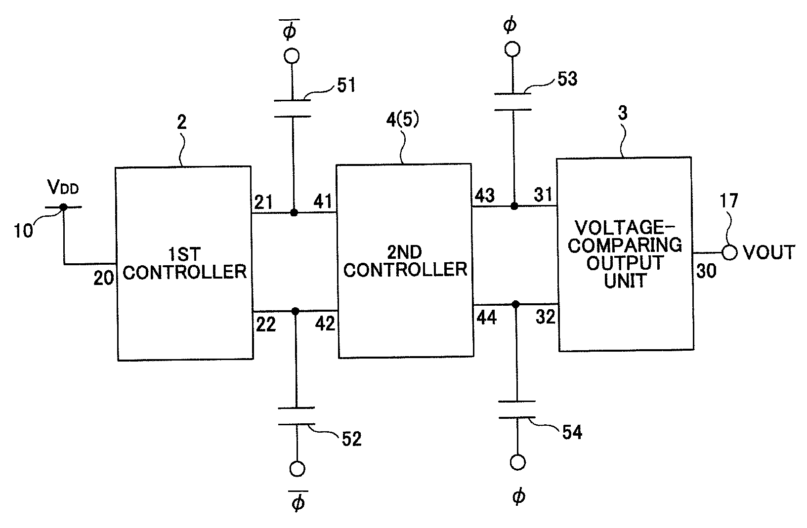
[0101]FIG. 9 shows a block diagram of a voltage generating circuit using a 2-stage charge pump circuit according to an embodiment of the present invention. FIG. 10 shows a circuit diagram illustrating the principle of the charge pump circuit according to the present embodiment.

[0102]The 2-stage charge pump circuit includes a first control unit 2, a second control unit 4(5), and a voltage comparison output unit 3. A capacitor is connected to each of the nodes between those units.

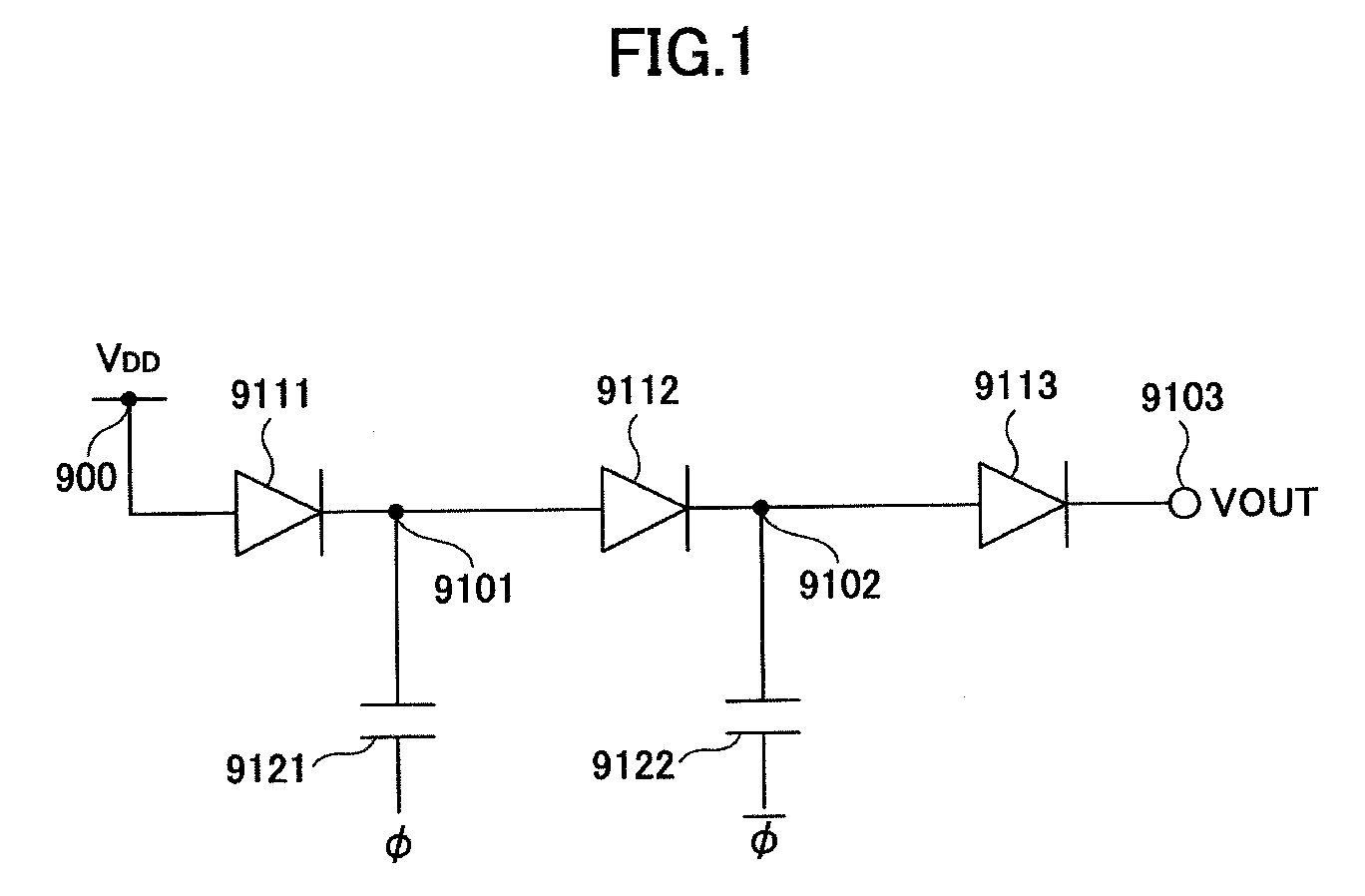
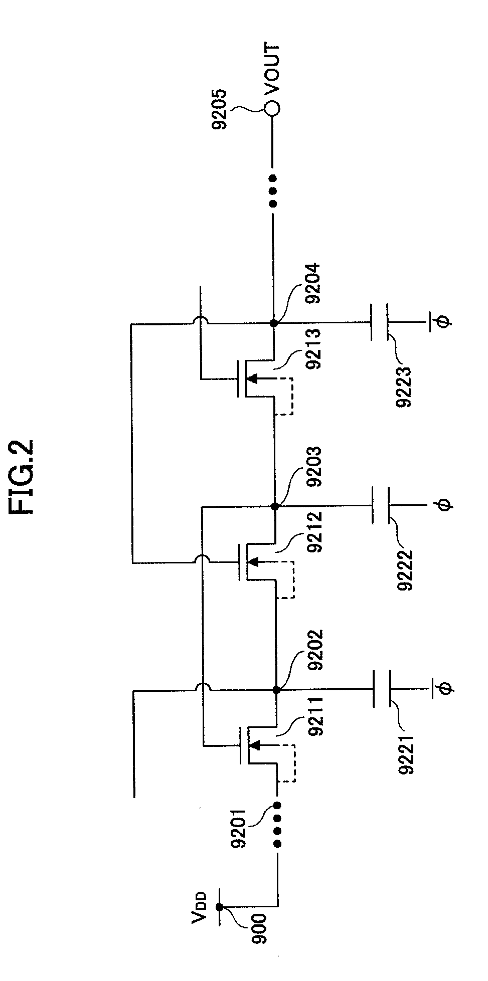
[0103]Referring to the principle diagram shown in FIG. 10, the 2-stage complementary component according to the present embodiment includes a first charge transfer circuit and a second charge transfer circuit. The first charge transfer circuit includes plural CTS's 101, 103, and 105 connected in series between a power...


PUM


Abstract

A charge pump provides high boosting efficiency with low power loss even with a heavy load. Plural charge transfer switches are connected in series forming two lines of charge transfer circuits operated by out-of-phase clock signals. Capacitors are connected to each of nodes in the charge transfer circuits. The charge transfer circuits include a first control unit, a second control unit, and a voltage comparison output unit. The second control unit includes a switch unit configured to selectively feed a signal from a previous-stage node or a later-stage node to the gate of a charge transfer switch in the second control unit, depending on the phase of the clock signal.

Description

BACKGROUND OF THE INVENTION[0001]1. Field of the Invention[0002]The present invention relates to voltage generating circuits that employ a charge pump circuit.[0003]2. Description of the Related Art[0004]Battery-operated portable devices have limited battery voltages, and so they are designed accordingly. However, such portable devices may sometimes require high voltages for driving a liquid crystal display (LCD) or a light-emitting diode (LED). The most common way of obtaining such high voltages or a large current stably is to use a DC / DC converter. DC / DC converters, however, require discrete elements such as coils, which prevents the reduction of implementation area.[0005]To overcome the above problem, a charge pump circuit is often used, which combines a transistor as a charge transfer element and a capacitor as a pumping element.[0006]FIG. 1 shows a Dickson type charge pump circuit that has conventionally been used as an easy way of constructing a charge pump booster circuit (vo...

Claims


Application Information

Patent Timeline
IPC IPC(8): G05F1/10
CPCH02M3/073
Inventor UEDA, YUUICHI
Owner RICOH ELECTRONIC DEVICES CO LTD
Why Eureka
Try Eureka