Combined installation for the production of biogas and compost, and method of switching a fermenter in a like installation between biogas production and composting

a technology of biogas and compost, which is applied in the direction of biomass after-treatment, energy input, settling tank feed/discharge, etc., can solve the problems of clogging of valves and detriment to consumers

Inactive Publication Date: 2009-09-24
BEKON ENERGY TECH GMBH & CO KG
View PDF10 Cites 18 Cited by
  • Summary
  • Abstract
  • Description
  • Claims
  • Application Information

AI Technical Summary

Benefits of technology

[0015]Due to the provisions of claim 13, biogas production and processing are maintained for as long as possible even while the fermentation process is terminated by purging with waste gas containing carbon dioxide, i.e., the biogas / waste gas mixture of the fermenter continues to be supplied to the biogas consumer until the quality of this mixture drops below a predetermined degree, before the fermenter is then switched over for composting of the fermented biomass contained in it. Only when the methane concentration in the biogas outlet drops below an upper limit, the biogas line leading to the biogas consumer is disconnected from the biogas outlet. After this, the biogas / waste gas mixture containing only a small quantity of methane is discharged via a waste gas chimney. This is carried out until the methane concentration has dropped to a lower limit at which virtually no methane is contained in the biogas / waste gas mixture any more. Afterwards the fermenter is purged not with waste gas containing carbon dioxide but with fresh air, and discharging the waste gas / biogas / fresh air mixture via the waste gas chimney is continued until the carbon dioxide concentration in the waste gas / biogas / fresh air mixture has dropped to a first limit. Only then the fermenter is switched over for composting. After termination of the composting process, the fermenter may be opened in order to unload the spent biomass and again charge the fermenter with fresh biomass. As a result of composting following fermentation, it is possible to open the fermenter for its unloading and reloading in the absence of any risk.

Problems solved by technology

This involves the drawback that it is necessary, for safety reasons, to prevent an explosive biogas / air mixture from being created while the individual fermenters are being loaded and unloaded.
As a result of filtering, substances possibly detrimental to the consumers, which might result in clogging of valves, for instance, are removed to the largest possible extent.

Method used


Image

  • Combined installation for the production of biogas and compost, and method of switching a fermenter in a like installation between biogas production and composting
  • Combined installation for the production of biogas and compost, and method of switching a fermenter in a like installation between biogas production and composting
  • Combined installation for the production of biogas and compost, and method of switching a fermenter in a like installation between biogas production and composting

Examples


first embodiment

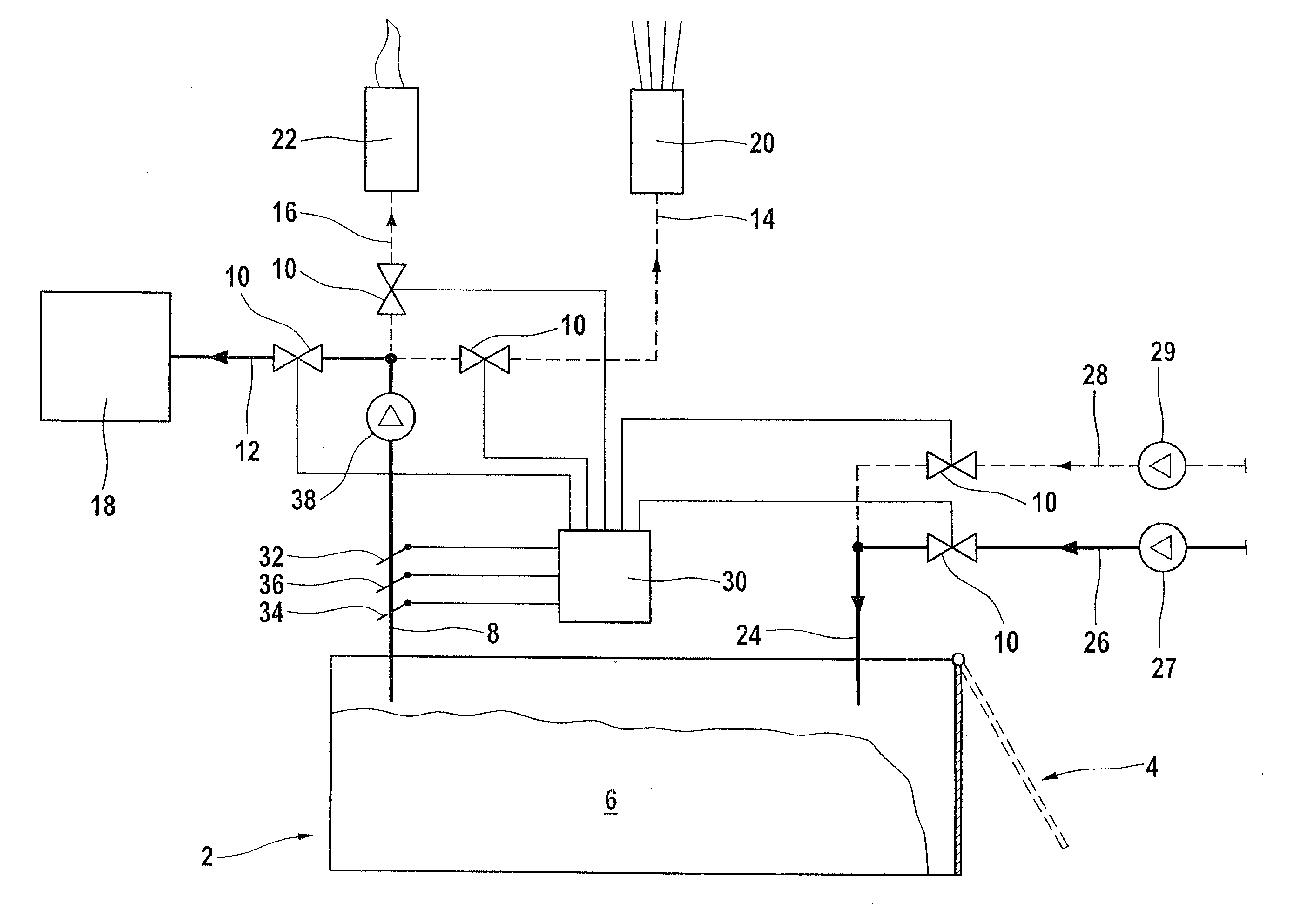
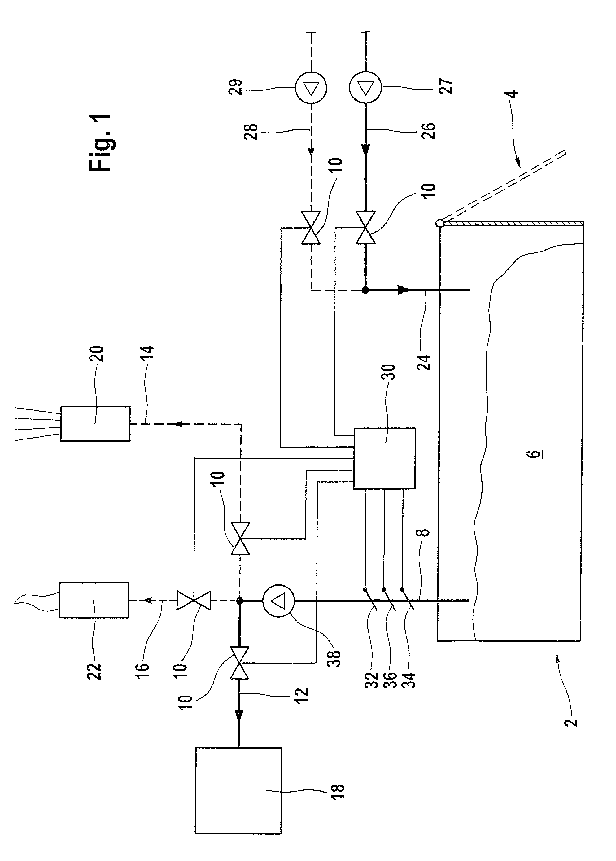
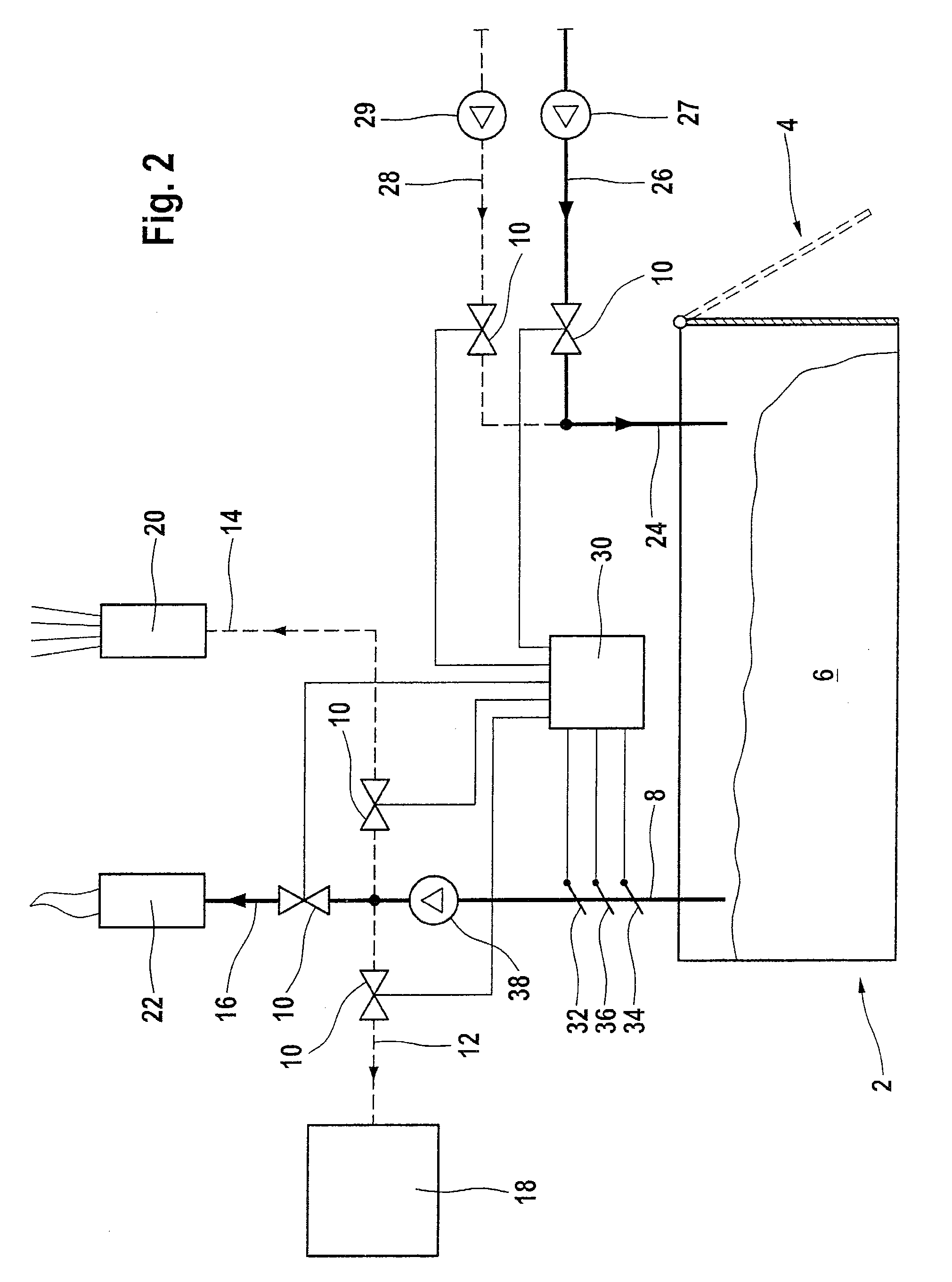
[0032]FIGS. 1 to 7 show a combined installation according to the present invention including a single fermenter 2. The fermenter 2 has a cuboid shape and is constructed approximately in the form of a prefabricated garage. The fermenter 2 can be filled with biomass 6 and emptied again by means of a tractor shovel through a loading and unloading opening 4 which extends over one of the end faces of the cuboid fermenter 2. Reference is made to WO 02 / 06439 with regard to details of the construction of the fermenter 2.

[0033]The fermenter 2 further includes a biogas outlet 8 adapted to be connected via valves 10 to a biogas line 12, a first biogas / waste gas line 14 and a second biogas / waste gas line 16. The biogas line 12 leads to a block-type thermal power station 18 constituting a biogas-utilising means. The first biogas / waste gas line 14 leads to a biogas / waste gas chimney 20. The second biogas / waste gas line 16 leads to a waste gas flare 22. Furthermore, the fermenter 2 includes a purg...

third embodiment

[0044]FIGS. 9 to 15 show a combined installation according to the present invention, in which three fermenters 2-1, 2-2 and 2-3 (in the following collectively designated as “2-i”) are provided in parallel operation. Mutually corresponding components are provided with the same reference symbols. In the combined installation shown in FIGS. 9 to 15, each of the three fermenters 2-i is provided with a purging gas inlet 24-1, 24-2 and 24-3, respectively, each of which may be shut off by a valve 10. The three purging gas inlets 24-i are combined to form a common purging gas inlet 42. A waste gas line 26 and a fresh air line 28, each of which may be shut off by a valve 10, open into the common purging gas inlet 42.

[0045]The three fermenters 2-i are each provided with a respective biogas outlet 8-18-2 and 8-3 that are each adapted to be shut off by a respective valve 10. The first biogas / waste gas line 14 to the waste gas chimney 20 and the second biogas / waste gas line 16 to the waste gas f...


PUM

PropertyMeasurementUnit
temperatureaaaaaaaaaa
concentrationaaaaaaaaaa

Abstract

A combined installation is disclosed for the production of biogas and compost, including a dry fermentation fermenter for producing biogas in a batch mode, a biogas outlet, a purging gas inlet, a biogas line connected to the biogas outlet, a waste gas line, a waste gas chimney connected to the biogas outlet via a first biogas/waste gas line, a waste gas flare connected to the biogas outlet via a second biogas/waste gas line, a fresh air line connected to the purging gas inlet, a control means for connecting the biogas outlet to the biogas line or the biogas/waste gas chimney via the first biogas/waste gas line or the waste gas flare via the second biogas/waste gas line and for connecting the purging gas inlet to the waste gas line or the fresh air line, and a measurement means connected to the control means for detecting methane and carbon dioxide concentrations.

Description

BACKGROUND OF THE INVENTION[0001]The invention relates to a combined installation for the production of biogas and compost from biomass, including at least one fermenter according to the principle of dry fermentation, according to claim 1, and to a method of switching a fermenter in a like installation between biogas production and composting, according to claim 13.[0002]So-called “dry fermentation” allows pourable biomasses from agriculture, from biological waste and from communal cultivated areas to be converted to methane without having to convert the materials to a liquid substrate which can be pumped. Biomasses having a dry substance content of up to 50% can be fermented. This dry fermentation method is described, for example, in EP 0 934 998.[0003]In the case of “dry” fermentation, the material to be fermented is not stirred into a liquid phase as is the case, for example, with liquid fermentation of organic waste. Instead, the fermentation substrate which has been introduced ...

Claims


Application Information

Patent Timeline
Patent Type & Authority Applications(United States)
IPC IPC(8): C12Q3/00C12M1/36
CPCC05F17/0027C05F17/0294C12M21/04Y02E50/343C12M23/36C12M23/58C12M41/34C12M21/16Y02P20/145Y02P20/129C05F17/957C05F17/50Y02E50/30Y02W30/40
Inventor LUTZ, PETER
Owner BEKON ENERGY TECH GMBH & CO KG
Why Eureka
Try Eureka