[0004]A prosthetic
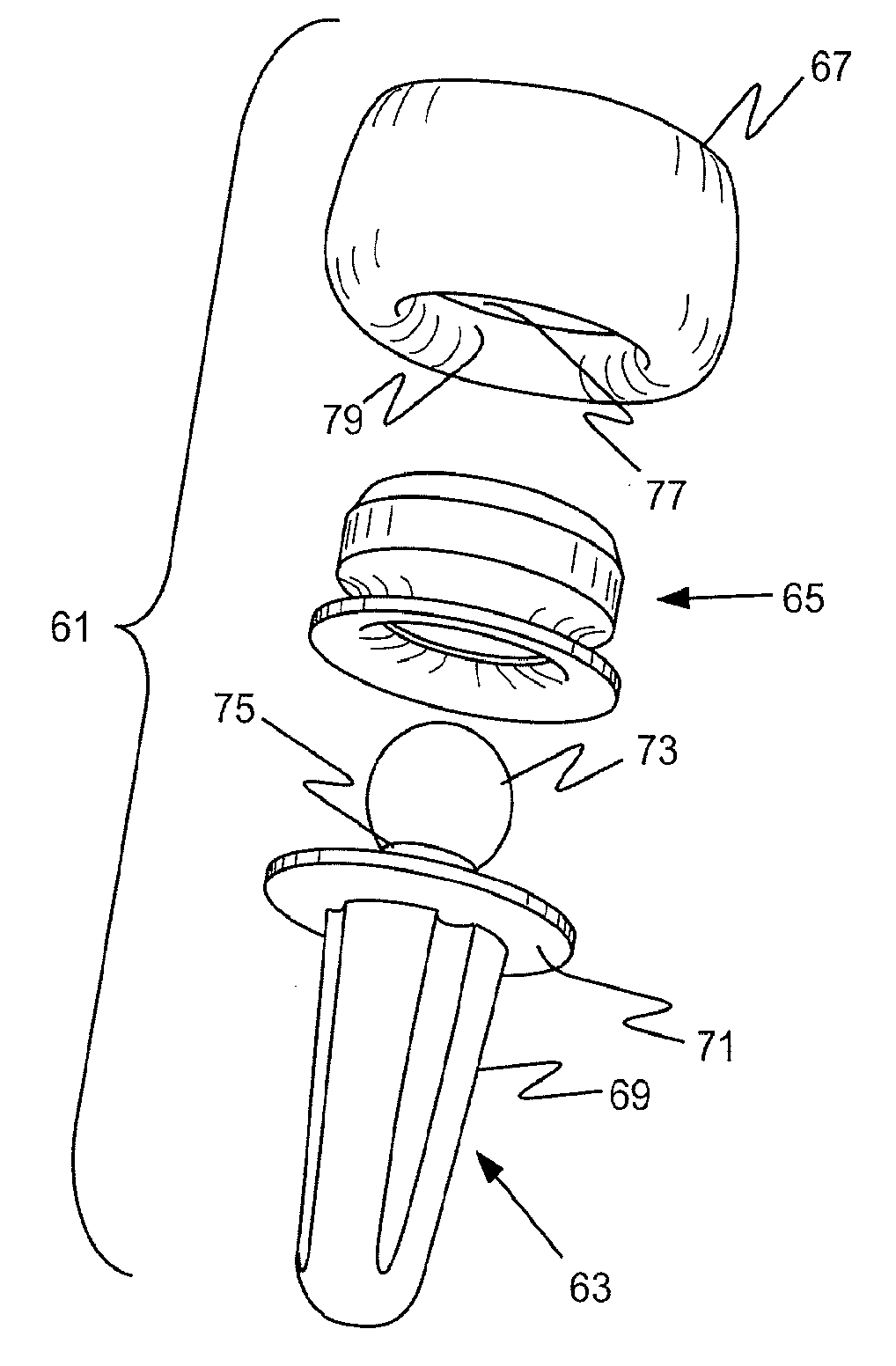
implant for implantation at a biological joint utilizes an integral, one-piece polymeric insert to join a
metal stem having a connector at one end to a head made of brittle crystalline material, particularly pyrocarbon-coated graphite. The head is formed with an entrance to an interior cavity of a size such that at least a portion of the polymeric insert must be elastically deformed to completely enter the cavity. The insert also has a cavity with an entrance region that is smaller than a corresponding dimension of an integral connector provided at the end of the
metal alloy stem. The proportioning of the components is such that the polymeric insert preferably achieves an
interference fit within the cavity of the pyrocarbon-coated head when mated, and the properties and
dimensioning of the insert are such that it can also accommodate small tolerances in the thickness of a pyrocarbon-coated interior cavity of the head and yet produce a strong composite subassembly. The properties of the polymeric insert are chosen to accommodate the entry of the connector through the smaller entrance region by elastically deforming. Depending upon the ultimate arrangement desired, the proportioning may be such that the insert, upon return to its original physical configuration, may result in an
interference fit at certain juxtaposed surfaces. Generally, the design will be such that, during
assembly, the elastic limit of the polymeric material will not be exceeded so no significant plastic flow will occur; to facilitate the final
mating of a subassembly of two components with the remaining component, i.e. either the
metal alloy stem element or the brittle crystalline head, a circumferential relief region is provided. The stem can be designed with a neck of a specific length so that the head will either (a) seat on a
flange that is a part of the stem or (b) pivot over a desired length of arc on a spherical connector at the end of the stem.
[0005]In a particular aspect, the invention provides a prosthetic implant for implantation into a resected bone, which implant comprises a metal stem element which has a connector at one end that is shaped with a reentrant region of reduced dimension, an integral one-piece polymeric insert which has a central cavity that receives said connector, and a head formed of brittle crystalline material having a central cavity being proportioned to receive said insert, said head cavity having an entrance of a size such that at least a portion of said polymeric insert must elastically deform inward to enter said cavity, said insert central cavity being formed with means for interengaging with said connector which requires radially outward deformation of at least a portion of said insert to lock said insert and said connector in engagement, and means providing a circumferential relief region into which a portion of said polymeric insert can elastically deform, and said integral polymeric insert being made of polymeric material having an elasticity, such that (a) it can deform radially inward sufficient to facilitate its entry into said head cavity and then return to shape, (b) it can deform radially outward to facilitate
assembly with said connector and then return to shape, and (c) once assembled with both said head and said stem connector, disassembly cannot inadvertently occur, with said final assembly being facilitated by said relief region location.
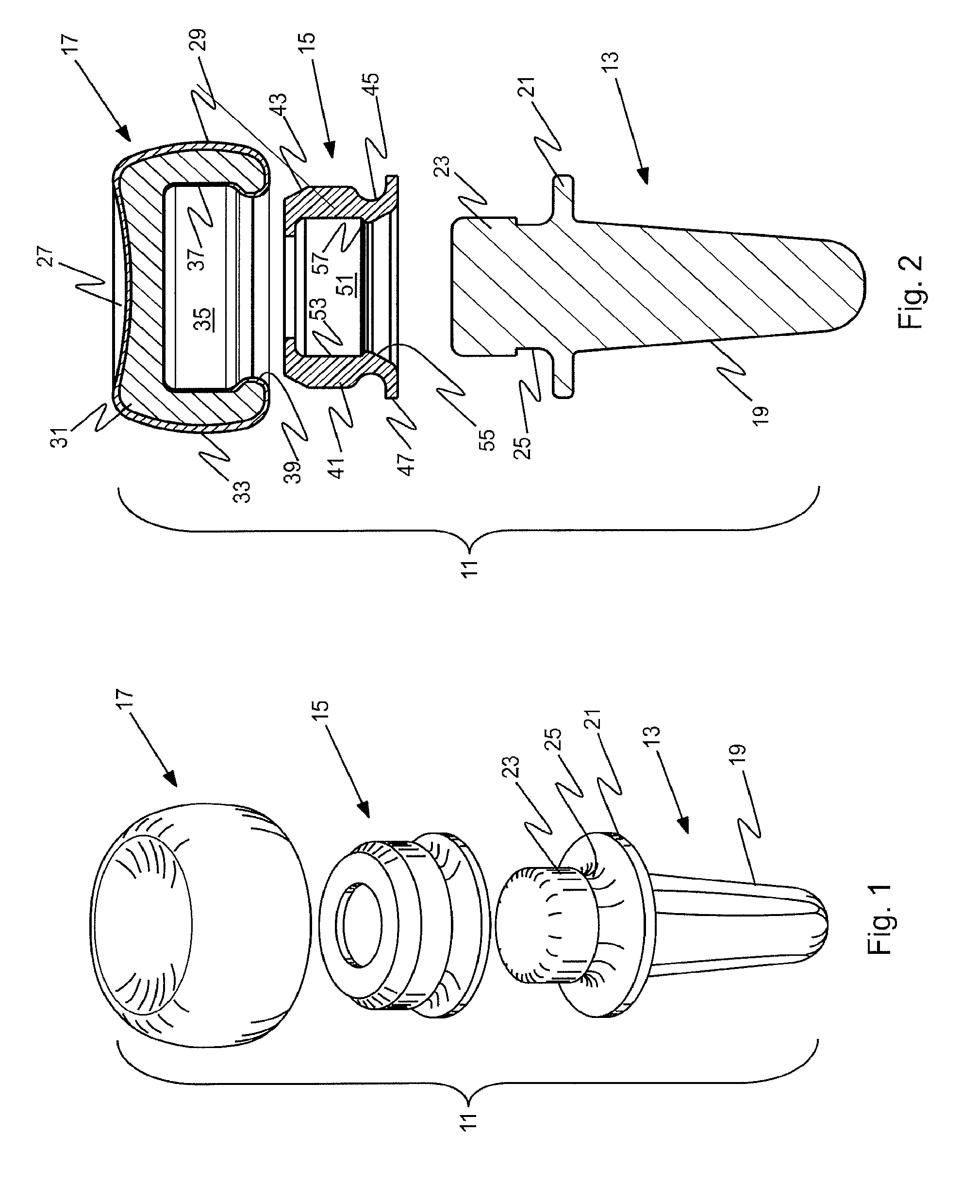
[0006]In a more particular aspect, the invention provides a prosthetic implant for implantation into a resected bone at a joint, which implant comprises a metal stem element which has a connector at one end that is shaped with a reentrant region of reduced dimension, an integral one-piece polymeric insert which has an interior cavity that receives said connector and a
flange that circumscribes an entrance to said cavity, and a head having an exterior
articular surface and an interior cavity proportioned to receive said insert, said head being formed from a
graphite substrate having interior and exterior pyrocarbon surfaces, said head cavity having an entrance formed by a reentrant entrance lip of a lesser inner
diameter and a size such that said polymeric insert must elastically deform radially inward to enter said cavity, said polymeric insert cavity having an entrance region of a size smaller than said connector and having an outer groove which receives said head entrance lip and is proportioned to provide an annular gap in said groove, and said integral polymeric insert being made of polymeric material having an elasticity, such that (a) it can deform radially inward sufficient to facilitate its entry into said head cavity and return to shape, (b) its entrance region can deform radially outward to facilitate assembly with said connector, and (c) once assembled with both said head and said stem connector, disassembly cannot inadvertently occur.
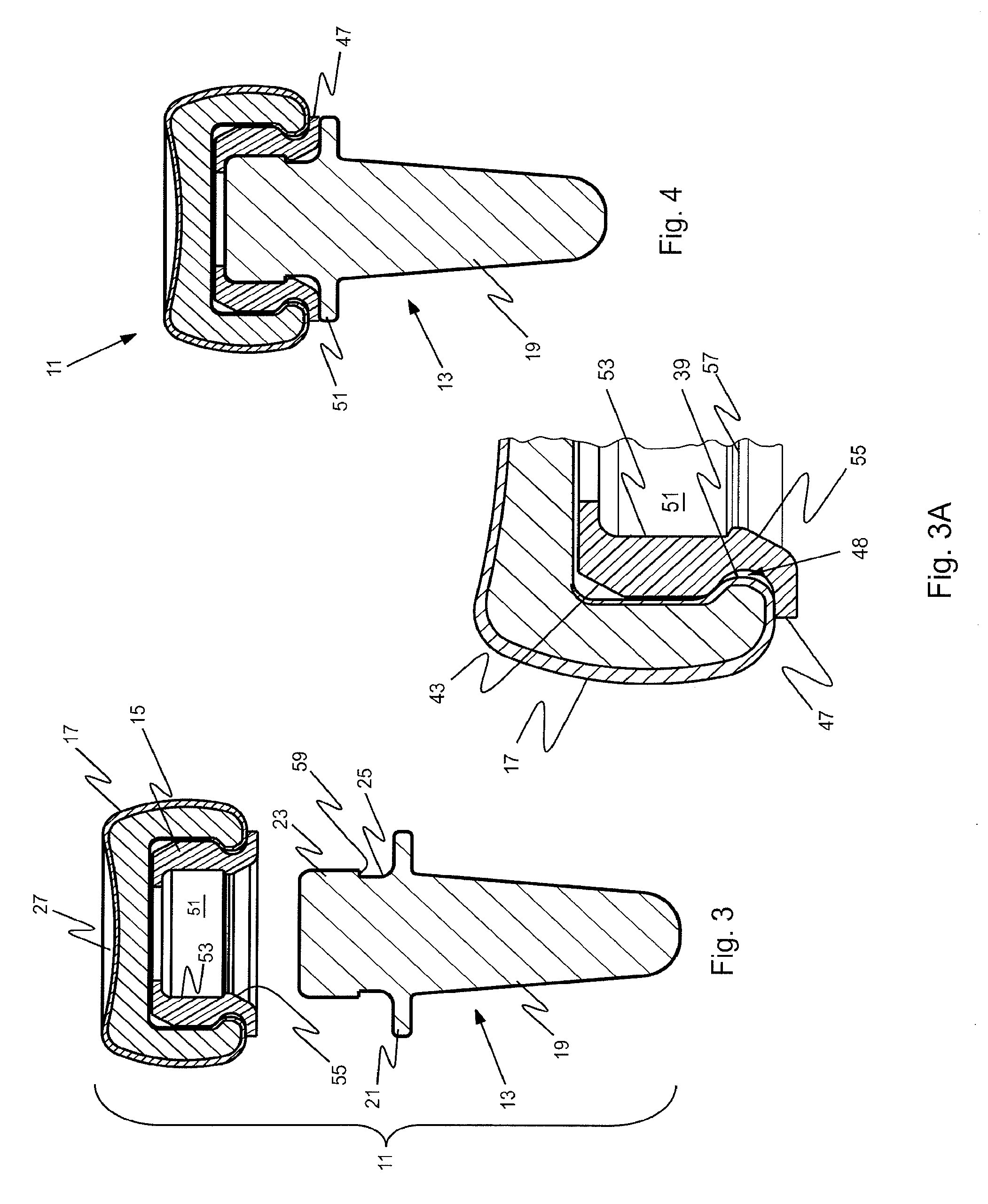
[0007]In another particular aspect, the invention provides a method for forming a prosthetic implant, which method comprises providing a
metal alloy stem element which has a connector at one end that is shaped with a region of reduced diametric dimension, providing a head of crystalline, brittle material having a cavity formed with an entrance of reduced
diameter, providing an integral polymeric insert that is proportioned to seat within said cavity in said head, which insert has an interior central cavity that is proportioned to receive said connector at the end of said stem element and to interengage therewith at said connector region of reduced diametric dimension, forming a subassembly by
mating said polymeric insert with said head by
insertion of said insert through said entrance into said head cavity in a manner in which the polymeric material deforms elastically radially inward to facilitate its entry and returns to shape within said head cavity, and then completing said prosthetic implant by
mating said subassembly with said stem element by inserting said connector into said interior cavity within said polymeric insert by causing said polymeric material to elastically deform radially outward at said interengaging means where it is accommodated by a circumferential relief region and then to return to a configuration having an interior
diameter which thereafter prevents inadvertent disassembly of said head subassembly from said stem element.

