Liquid droplet ejection head and method for manufacturing the same

a technology of ejection head and droplet, which is applied in the direction of metal-working equipment, printing, writing implements, etc., can solve the problems of affecting the quality of resin sheets, so as to improve the flexibility of the damper wall, shorten the outflow passage, and increase the damper

Active Publication Date: 2009-10-01
BROTHER KOGYO KK
View PDF2 Cites 5 Cited by
  • Summary
  • Abstract
  • Description
  • Claims
  • Application Information

AI Technical Summary

Benefits of technology

[0021]In accordance with this configuration, since the resin portion is placed inside the common liquid chamber, the outflow passage can be shortened by the thickness of the resin portion while improving the flexibility of the damper wall to increase the damper effect. Therefore, the liquid passage resistance of the outflow passage can be reduced, and the drive voltage of the actuator can be lowered. In addition, the sealing between the common liquid chamber and the damper chamber can be secured.
[0022]The step of forming the damper plate includes a step of forming a substrate formed by stacking a resin layer on the base portion before the step of forming the damping space on the base portion, and in the step of forming the resin portion, the resin layer is etched such that the resin portion is left on the surface of the base portion which surface faces the manifold plate and at the portion above and around the damping space. In accordance with this configuration, the damper plate having the resin portion of the above shape can be formed easily and surely.
[0023]In the step of forming the damping space on the base portion, a recess is formed as the damping space on a surface of the base portion which surface is opposite the surface facing the common liquid chamber, and a part of the base portion remains as a thin portion on a common liquid chamber side of the base portion; and in the step of forming the resin portion, the damper wall is constituted by the thin portion and a covering portion which is a part of the resin portion and covers the thin portion. In accordance with this configuration, the thin portion of the damper plate is reduced in thickness to increase the effect of damping the backward components of the ejection pressure. With this, even if the gap is formed on the thin portion, the communication between the common liquid chamber and the damper chamber via the gap can be prevented by the resin portion.
[0024]Moreover, the step of forming the damping space on the base portion may include: a step of masking the damper plate except for a region corresponding to the recess; and a step of half-etching the region corresponding to the recess by etching liquid. In this configuration, although the peripheral portion of the thin portion tends to be the thinnest portion by the etching liquid, the thinnest portion is covered with the resin portion which is larger in the contour shape than the thin portion in plan view. Therefore, the communication between the common liquid chamber and the damper chamber can be effectively prevented even at the thinnest portion where the gap tends to be formed.
[0025]In the step of forming the damping space on the base portion, a through hole penetrating through the base portion is formed as the damping space; and in the step of forming the resin portion, the damper wall is constituted by a covering portion which is a part of the resin portion and covers one opening of the through hole. In this configuration, the sealing of the common liquid chamber can be secured by the resin portion, and the damper wall having high damper effect can be constituted by the resin portion which is elastically deformable.

Problems solved by technology

In a case where the backward components of the ejection pressure are transmitted backward from the pressure chamber to the common ink chamber, pressure fluctuations caused by the backward components are absorbed by elastic deformation of the damper wall, and this damps the pressure fluctuations in the common ink chamber.
However, an ingot of a metal material that is a raw material of the damper plate contains a small amount of impurities including an additive injected thereto at the time of manufacturing.
Therefore, in a case where the thickness of the damper wall is reduced to be the same level as the particle diameter of the impurity, the impurity in the damper wall may fall off, and this may cause a partial damage or crack on the damper wall.
Moreover, to achieve a desired liquid passage resistance of the outflow passage, it is necessary to accurately process a cross-sectional shape of the outflow passage, so that the step of processing the outflow passage with respect to the resin sheet may require time, labor, and cost.

Method used


Image

  • Liquid droplet ejection head and method for manufacturing the same
  • Liquid droplet ejection head and method for manufacturing the same
  • Liquid droplet ejection head and method for manufacturing the same

Examples


embodiment 1

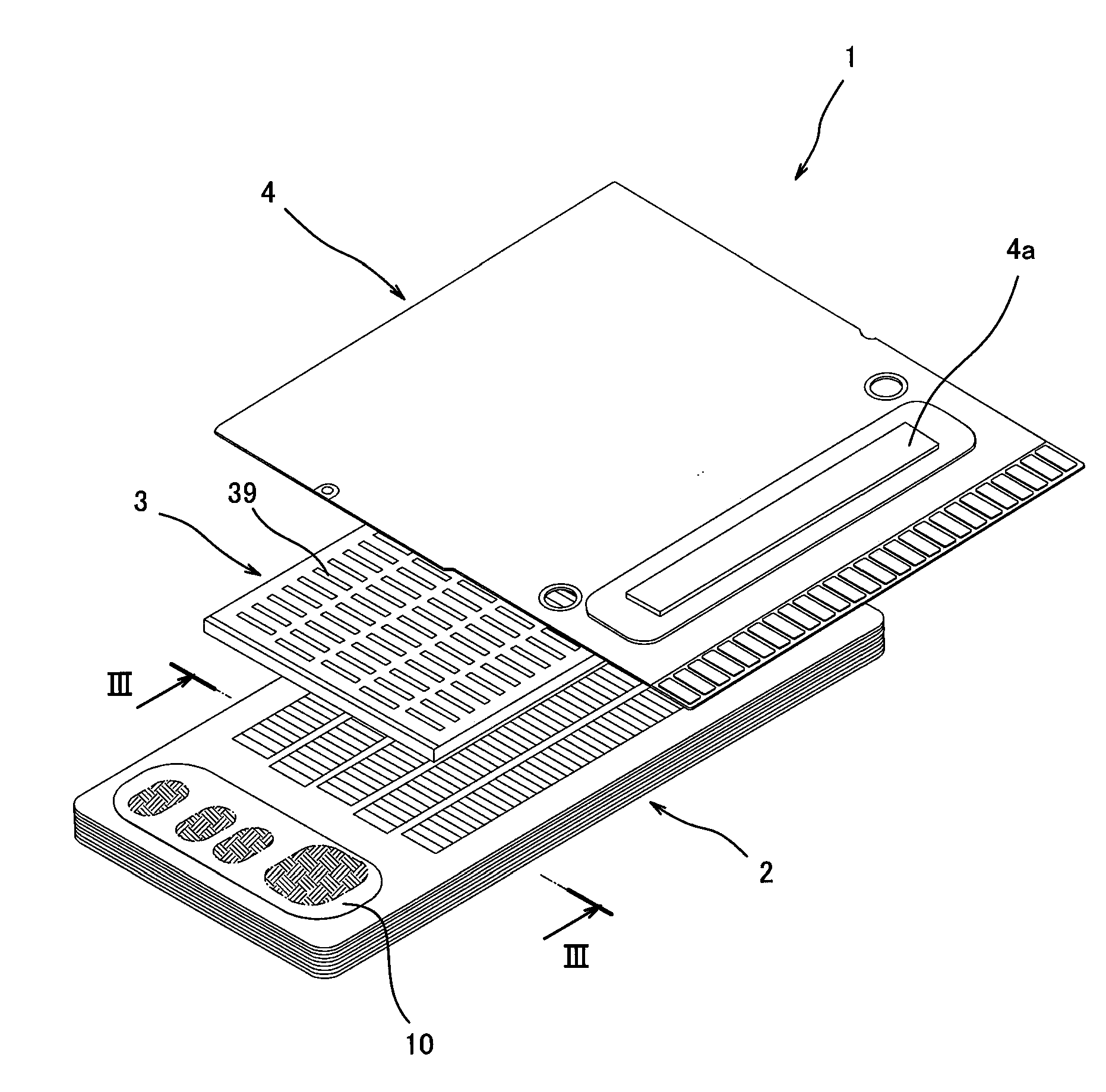
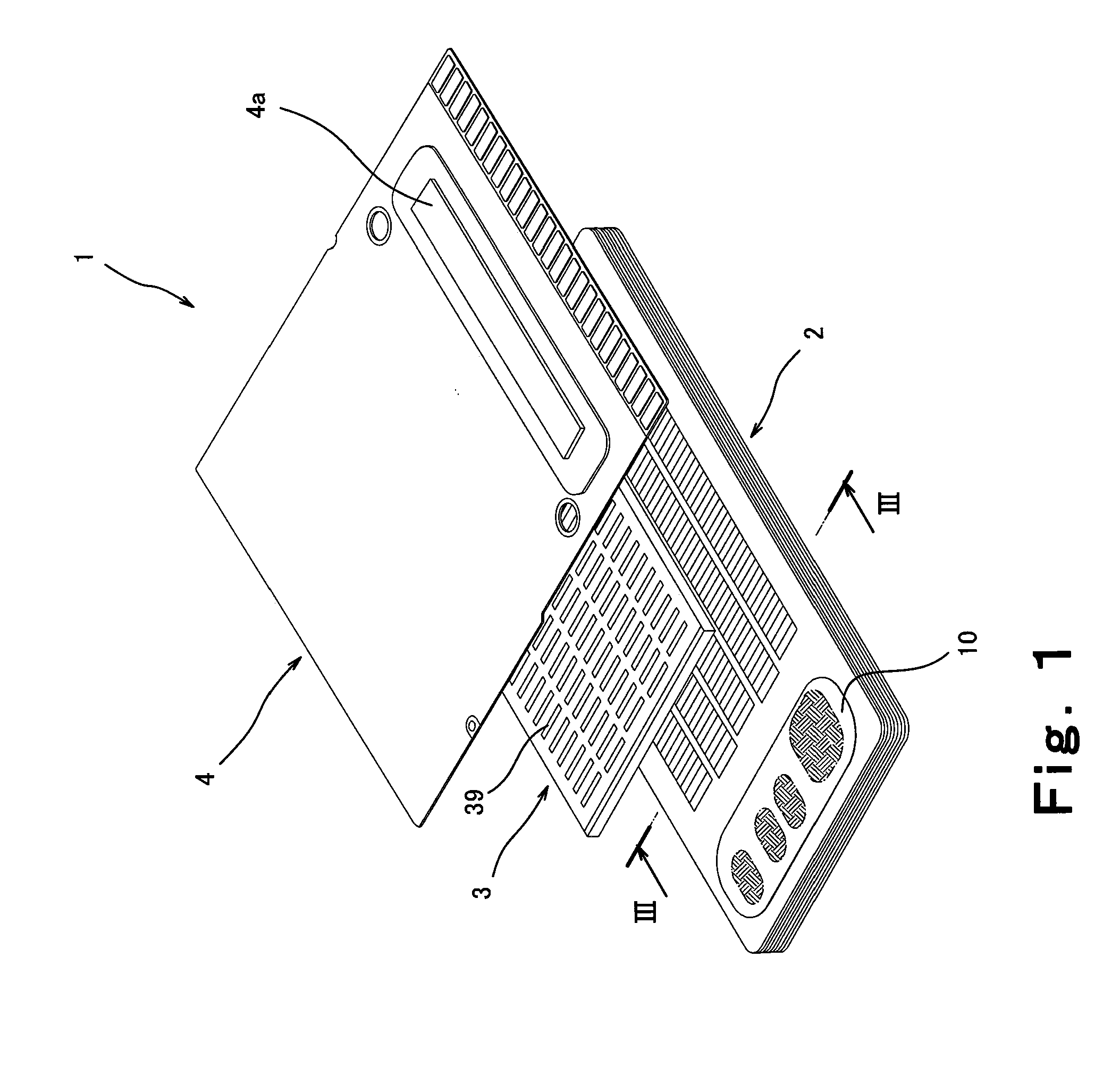
[0035]FIG. 1 is an exploded perspective view of the ink jet head of the present invention. As shown in FIG. 1, an ink jet head 1 (liquid droplet ejection head) includes a passage unit 2 constituted by stacking a plurality of plates, and a piezoelectric actuator 3 (energy generator) stacked on the passage unit 2 so as to overlap the passage unit 2 from above. A flexible wire member 4 is joined to the actuator 3 so as to overlap the actuator 3 from above. A plurality of surface electrodes 39 are printed on an upper surface of the actuator 3. The surface electrodes 39 and terminals, not shown, exposed on a lower surface of the flexible wire member 4 are joined to each other via, for example, an electrically conductive material to be electrically connected to each other. An IC chip 4a (see FIG. 1) is mounted on the flexible wire member 4. The IC chip 4a incorporates a drive circuit configured to output an electric signal for driving the actuator 3 in accordance with print data.

[0036]FI...

embodiment 2

[0064]FIG. 6 is a partial cross-sectional view of an ink jet head 51 of the present invention. FIG. 7 shows a passage unit 52 in plan view, is a cross-sectional view taken along line VI-VI of FIG. 6, and is a plan view showing a state where the plates are adhesively stacked on one another when viewed from above the first manifold plate 14. Differences between Embodiments 1 and 2 will be mainly explained in the present embodiment. Same reference numbers are used for the same components, and a repetition of the same explanation is avoided.

[0065]As shown in FIGS. 6 and 7, in a damper plate 66, a damper through hole 71a having a width (Y-direction dimension) d4 is formed on the base portion 71, and a resin portion 72 including a covering portion 72b covering an upper opening of the damper through hole 71a is partially stacked on an upper surface of the base portion 71 to be located at a position where the damper through hole 71a is formed. The resin portion 72 has a width (Y-direction ...


PUM

PropertyMeasurementUnit
thicknessaaaaaaaaaa
thicknessaaaaaaaaaa
thicknessaaaaaaaaaa

Abstract

An object of the present invention is to provide a liquid droplet ejection head capable of securing sealing of a common liquid chamber and realizing a high damper effect while suppressing a driving energy of the liquid droplet ejection head. A passage unit includes manifold plates, and a damper plate which is stacked on the manifold plates and has a damper wall facing a common liquid chamber. The damper plate is constituted by a base portion having a damping space at a position corresponding to the manifold holes in plan view, and a resin portion stacked on the base portion. The resin portion is formed to cover at least a portion above and around the damping space to constitute the damper wall, be smaller in a contour shape than the common liquid chamber in plan view, and be stored in the manifold holes.

Description

CROSS-REFERENCE TO RELATED APPLICATION[0001]This application claims priority to and the benefit of Japanese Patent Application No. 2008-088923, filed Mar. 29, 2008, the entire disclosure of which is incorporated herein by reference.BACKGROUND OF THE INVENTION[0002]1. Field of the Invention[0003]The present invention relates to a liquid droplet ejection head, such as an ink jet head mounted on an ink jet printer, including a passage unit, and a method for manufacturing the liquid droplet ejection head.[0004]2. Description of the Related Art[0005]An ink jet head that is one example of a liquid droplet ejection head includes a passage unit and an actuator. Liquid passages are formed in the passage unit, and are constituted by: a plurality of nozzles configured to eject liquid droplets; a common ink chamber connected to a liquid supply source; a plurality of pressure chambers communicated with the common ink chamber; and an outflow passage which causes the pressure chamber and the nozzl...

Claims


Application Information

Patent Timeline
Patent Type & Authority Applications(United States)
IPC IPC(8): B41J2/04B21D53/76
CPCB41J2/055B41J2/14209B41J2/1609B41J2/1623B41J2/1629Y10T29/49401B41J2/1634B41J2002/14225B41J2002/14306B41J2002/14419B41J2/1631
Inventor ITO, ATSUSHI
Owner BROTHER KOGYO KK
Why Eureka
Try Eureka