Eureka AIR delivers breakthrough ideas for toughest innovation challenges, trusted by R&D personnel around the world.

Passive optical network system and operation method of the same

a passive optical network and operation method technology, applied in the field of configuration and operation of passive optical network systems, can solve the problems of increasing noise on the receiver side, reducing transmission distance, and dispersing distance between the olt, so as to reduce the power consumption of the communication apparatus, the system cost is not increased, and the dynamic range which can be covered by a single station can be expanded.

Inactive Publication Date: 2009-10-01
HITACHI LTD
View PDF0 Cites 52 Cited by
  • Summary
  • Abstract
  • Description
  • Claims
  • Application Information

AI Technical Summary

Benefits of technology

[0006]To provide a low-priced PON system, it is essentially required that facilities are shared, e.g., optical fiber is shared; the transmission performance is enhanced, and the number of subscribers to be accommodated is increased. When increasing the number of users to be accommodated, there may employed a method in which the number of branches is increased by sustaining the transmission distance of the existing PON. Alternatively, in addition to the increase of the branches, it is also considerable that the transmission distance of the PON is elongated to thereby accommodate new users more apart than the OLT.
[0007]In this situation, there arises a problem of dispersion in distance between the OLT as a carrier constituting the PON and the ONU installed in houses of users. In operation of the PON being used at present (i.e., a Gigabit-capable PON (GPON) of 2.4 Gbps), the OLT-ONU distance is about 20 kilometers (Km) or less in most case. However, it is known, in signal transmission at 10 Gbps or more which is to be assumed in the next-generation PON, that the transmission distance is lowered due to deterioration in the signal waveform and the increase in noise on the receiver side. It is hence difficult to secure the 20 km transmission without modifying the parts or components (technique) being used at present. To remove the difficulty, it is possible to employ a method in which the number of communicable users is increased by increasing the signal multiplexing degree on the optical fiber, a method in which transmission optical power is enhanced to compensate the branch loss by the splitter, and a method of introducing various parts and components described above. However, simultaneous introduction of these methods results in increase in the system cost.
[0008]Elongation of the OLT-ONU transmission distance in the PON leads to increase in the number of users (ONU) per OLT. It is therefore an object of the present invention to provide a configuration and an operation method of the PON in which the number of users to be accommodated can be increased by elongating the transmission distance while suppressing the increase in the system cost.
[0009]More specifically, the present invention provides a configuration and an operation method of the PON accommodating a large number of users on access lines by sharing optical fiber in which the transmission bit rate is changed according to the transmission distance of the optical section of each user to thereby expand the distance between a user (ONU) which can be accommodated and a carrier station (OLT), i.e., a dynamic range which can be covered by a single station) and the transmission bit rate is suppressed when the transmission distance is long to thereby reduce power consumed by the communication apparatus.
[0010]In order to solve the problem above, in the configuration of the PON of the present invention, the transmission distance and the transmission time between the OLT and the ONU are measured during the operation of the PON. If the distance and the time are short, the communication is carried out at a higher transmission speed to increase the number of users to be accommodated. Additionally, in a case wherein the OLT-ONU distance is long, if the communication is conducted at a high transmission speed, the consumption power and the cost are increased. Hence, to increase the number of accommodated users communicatable in a state in which a predetermined communication quality is secured, the measurement is carried out by conducting the communication using a lower transmission speed. According to results of the measurement, the transmission speed between the OLT and the ONU is selected for communication.
[0014]In the PON, by changing the transmission bit rate according to the transmission distance of the optical section of each user, the distance between a user (ONU) which can be accommodated and a carrier station (OLT), namely, a dynamic range which can be covered by a single station can be expanded. It is also possible to provide a configuration of the PON and a method of operating the same in which by suppressing the transmission bit rate when the transmission distance and / or the transmission speed are / is long, power consumed by the communication apparatus can be lowered. Since expensive constituent components necessary for the high-speed transmission are not required, the system cost is not increased. If the transmission distance and / or the transmission speed are / is short, the communication is carried out at a higher transmission speed, and hence an increased number of users can be accommodated.

Problems solved by technology

In this situation, there arises a problem of dispersion in distance between the OLT as a carrier constituting the PON and the ONU installed in houses of users.
However, it is known, in signal transmission at 10 Gbps or more which is to be assumed in the next-generation PON, that the transmission distance is lowered due to deterioration in the signal waveform and the increase in noise on the receiver side.
It is hence difficult to secure the 20 km transmission without modifying the parts or components (technique) being used at present.
However, simultaneous introduction of these methods results in increase in the system cost.

Method used


Image

  • Passive optical network system and operation method of the same
  • Passive optical network system and operation method of the same
  • Passive optical network system and operation method of the same

Examples


Embodiment Construction

[0025]Referring now to the drawings, description will be given in detail of structure and operation of a PON according to the present invention, specifically, in a situation wherein the PON includes the GPON stipulated by ITU-T Recommendation G.984 and the 10GPON handling data at a transmission speed which is four times that of the GPON and which will be expectedly introduced in the future.

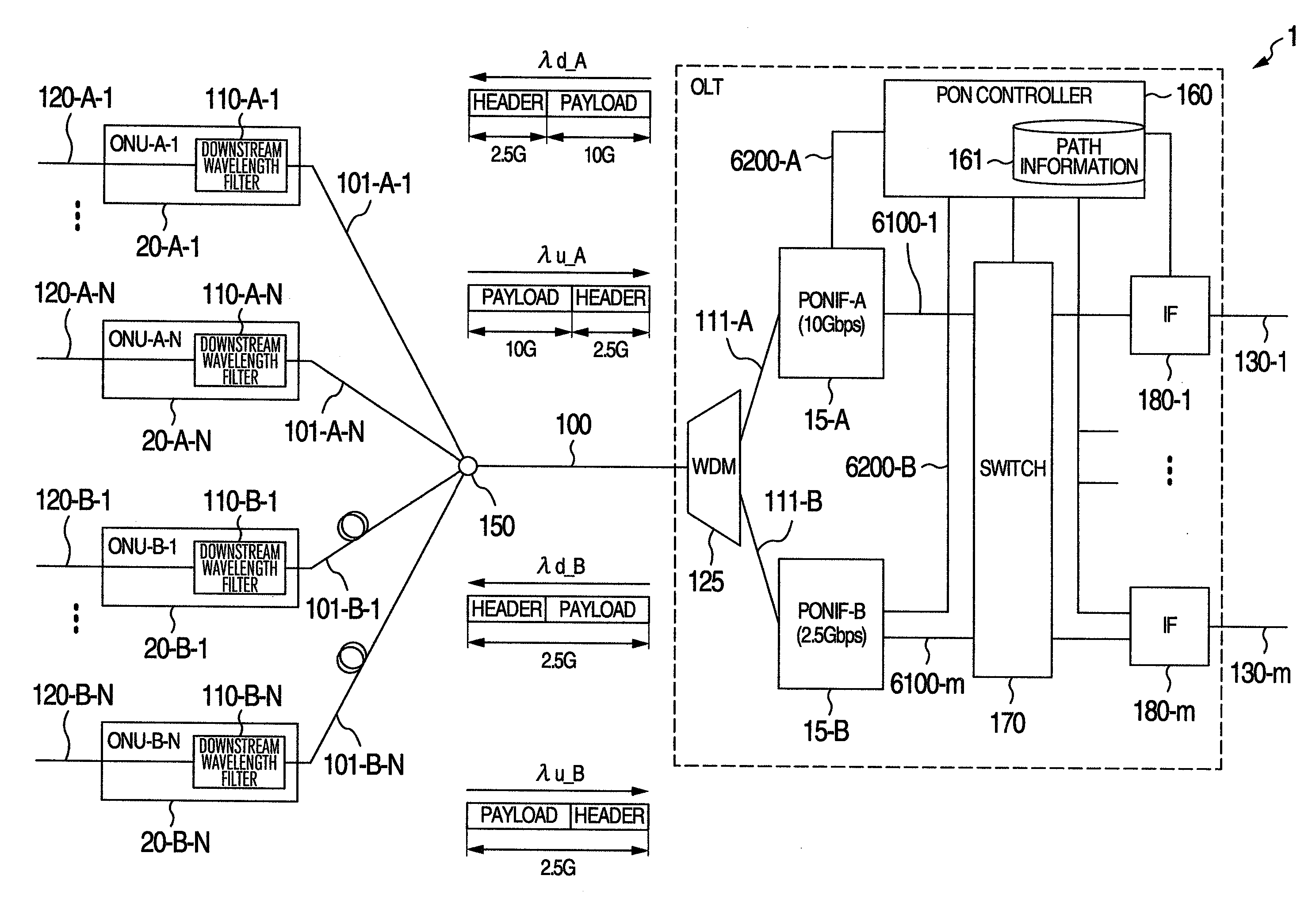
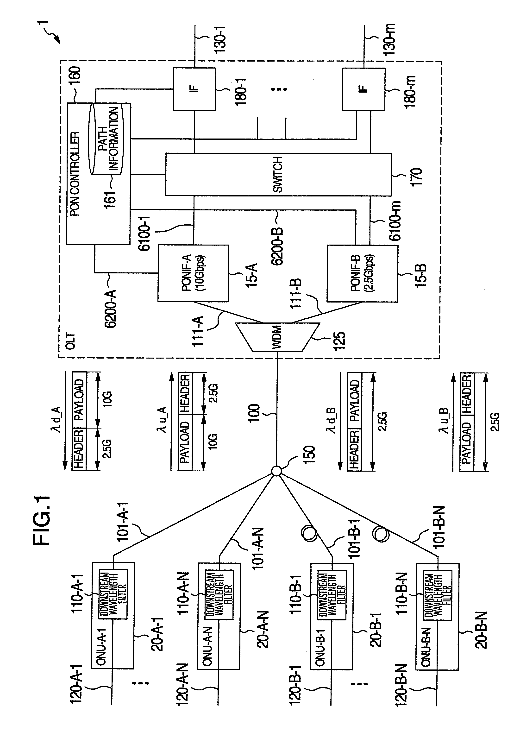
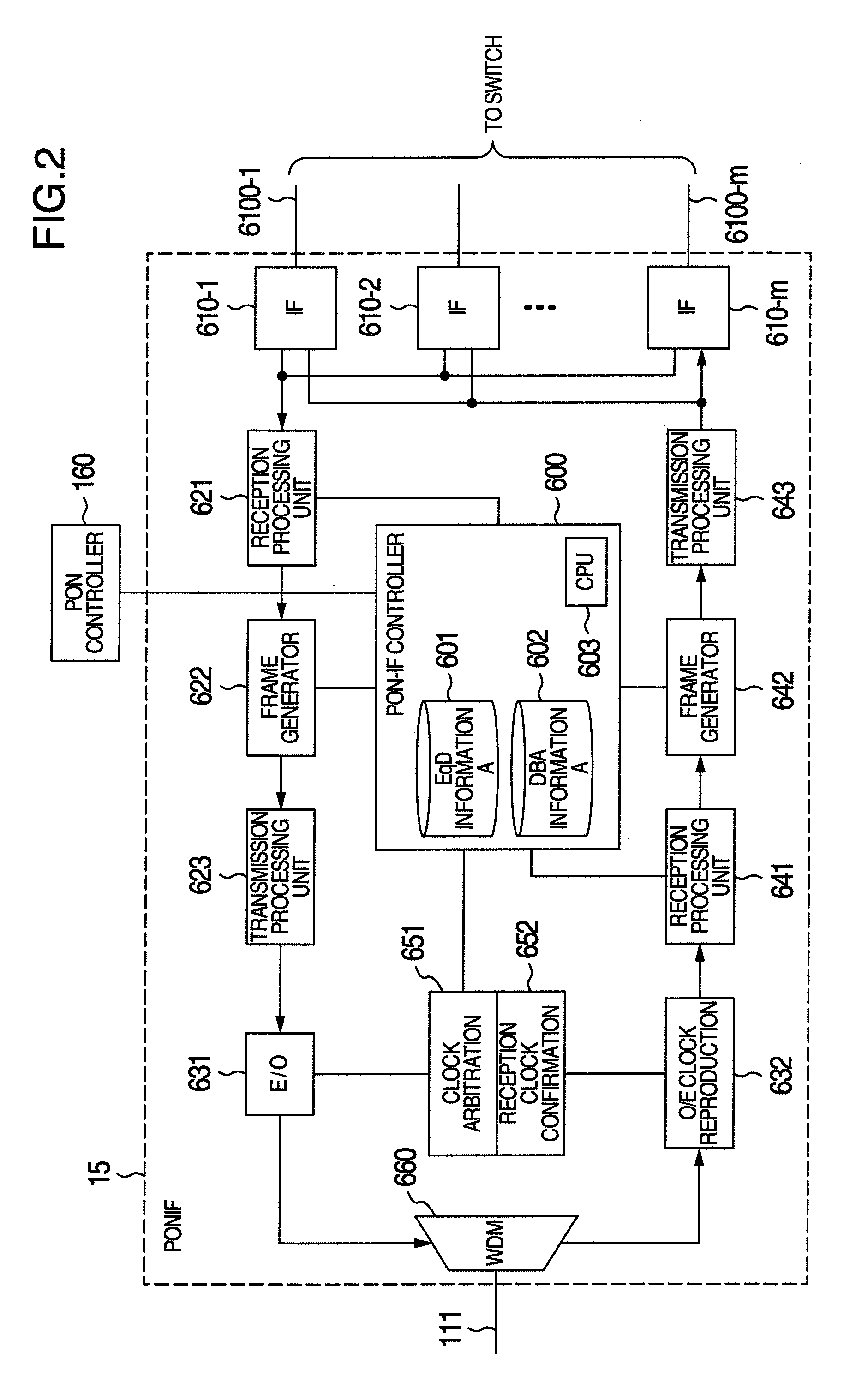
[0026]FIG. 1 shows an example of structure of an optical access network employing the PON.

[0027]This network is configured on assumption that variable data is processed by use of a time-division multiplexing scheme as in the GPON. Data (payload) is communicated between an OLT 10 and each ONU 20 at a transmission speed of 2.5 Gbps (precisely, 2.48832 Gbps, but will be abbreviated as 2.5 Gbps hereinbelow) in the GPON and 10 Gbps (precisely, 9.95328 Gbps, but will be abbreviated as 10 Gbps hereinbelow) in the 10GPON. Headers are communicated between the OLT 100 and each ONU 20 at a transmission speed...


PUM


Abstract

In a passive optical network system, in order that by measuring a transmission distance and a transmission time between an OLT and an ONU in operation of the system, if the distance or the time is short, communication is conducted at a high transmission speed to increase a capacity of user; if the distance or the time is long, communication is conducted at a low transmission speed to increase the capacity of user communicating in a state in which a predetermined quality is secured, a main station includes a signal communication circuit to communicate with subsidiary stations at a first or second transmission speed and a controller to measure a transmission distance or a transmission time between the main station and each subsidiary station. Based on a result of the measurement, the controller selects a transmission speed for communication with the subsidiary station.

Description

INCORPORATION BY REFERENCE[0001]The present application claims priority from Japanese application JP2008-089126 filed on Mar. 31, 2008, the content of which is hereby incorporated by reference into this application.BACKGROUND OF THE INVENTION[0002]The present invention relates to a configuration and an operation method of a passive optical network system in which a plurality of subscriber connecting units shares an optical transmission line.[0003]Since the communication speed is increasing and the communication range is expanding also in access networks to connect subscribers to communication networks, it has been considered to introduce a Passive Optical Network system (to be referred to as PON system hereinbelow) prescribed by, for example, recommendations of International Telecommunications Union-Telecommunication Standardization Sector (to be referred to as ITU-T hereinbelow; ITU-T Recommendation G.984.1, G.984.2, G.984.3). The PON system is a system in which an Optical Line Ter...

Claims


Application Information

Patent Timeline
IPC IPC(8): H04J14/00H04L12/44
CPCH04J14/0282H04J3/0682
Inventor MIZUTANI, MASAHIKOYAJIMA, YUSUKE
Owner HITACHI LTD
Why Eureka
Eureka Blog
Learn More