Carrier core material for electrophotographic developer, carrier, and electrophotographic developer using the carrier

a carrier core material and electrophotographic technology, applied in the field of carrier core material for electrophotographic developers, electrophotographic developers, and electrophotographic developers, can solve the problems of large change in properties, low scattering matter magnetization of electrophotographic developers, and difficulty in obtaining the image quality and life of the above-described ferrite carrier, etc., to achieve stable image density and large changes in resistivity

Active Publication Date: 2009-10-01
MITSUI MINING & SMELTING CO LTD +1
View PDF5 Cites 10 Cited by
  • Summary
  • Abstract
  • Description
  • Claims
  • Application Information

AI Technical Summary

Benefits of technology

[0016]Therefore, it is an object of the present invention to provide a carrier core material for an electrophotographic developer which does not have large changes in resistivity from low bias to high bias, in which a result of having controllable magnetization does not cause carrier beads carry over to occur, and which can obtain a stable image density, a carrier, and an electrophotographic developer using the carrier.

Problems solved by technology

However, with these carriers, it is difficult to obtain the image quality and life of the above-described ferrite carriers.
However, it is pointed out that Li is easily affected by the surrounding environment, such as temperature and humidity, so that its properties greatly change.
However, this carrier for an electrophotographic developer suffers from the problem of having low scattered matter magnetization due to sintering unevenness.
However, such Li—Mn ferrite carriers suffer from the problem that usually resistivity is high, and that resistivity is reliant on electric field strength.
In carriers for an electrophotographic developer, just having a resistivity in a specific electric field strength in a specific range is insufficient.

Method used


Image

  • Carrier core material for electrophotographic developer, carrier, and electrophotographic developer using the carrier
  • Carrier core material for electrophotographic developer, carrier, and electrophotographic developer using the carrier

Examples


example 1

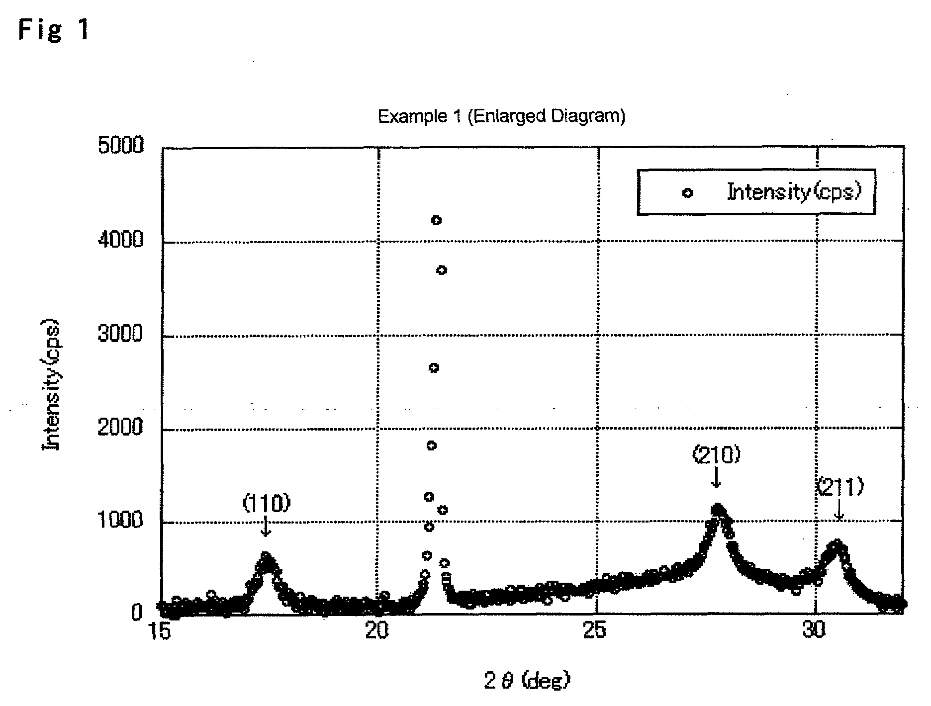
[0089]76.7 mol of Fe2O3, 13.3 mol of Li2CO3, and 3.33 mol of Mn3O4 were weighed out so that the Fe, Li, and Mn were in a predetermined weight ratio. The resultant mixture was charged with water so that the mixture had a solid content of 50%. Further, a 20% lithium silicate aqueous solution in terms of SiO2 was added so that the mixture contained 3,000 ppm of Si based on the solid content. The mixture was crushed using a bead mill. The crushed product was then preliminarily granulated using a spray dryer, and calcined in an air atmosphere at 1,000° C. The calcined product was further charged with water, a binder component, and a dispersant so that the solid content was 50%. The resultant mixture was crushed using a bead mill, and the crushed product was granulated using a spray dryer. The obtained granulated material was deashed in air at 650° C., and then the resultant product was sintered for 16 hours at 1,165° C. at an oxygen concentration of 1% by volume to obtain a sintered mate...

example 2

[0090]As shown in Table 1, a carrier core material having a volume average particle size of 35.1 μm was obtained in the same manner as in Example 1, except that 1.66 mol of Mn3O4 was used.

example 3

[0091]As shown in Table 1, a carrier core material having a volume average particle size of 35.5 μm was obtained in the same manner as in Example 1, except that 5 mol of Mn3O4 was used.


PUM


Abstract

A carrier core material for an electrophotographic developer including Li ferrite, maghemite, and Fe3O4, wherein a part thereof is substituted with Mn, Li content is 1 to 2.5% by weight, Mn content is 2 to 7.5% by weight, and silicon content is 25 to 10,000 ppm, the following equation (1) is satisfied when respective integrated strengths of spinel crystal structure (110), (210), (211), and (311) faces in X-ray diffraction are respectively I110, I210, I211, and I311, a resistivity R50 of 50 V across a 6.5 mm gap is 5×10⁷ to 7×10⁸Ω, and a resistivity R1000 of V across a 6.5 mm gap is 1×10⁷ to 8×10⁸Ω.
2<100×(I110+I210+I211)/I311<14   (1)

Description

BACKGROUND OF THE INVENTION[0001]1. Field of the Invention[0002]The present invention relates to a carrier core material for an electrophotographic developer, a carrier, and an electrophotographic developer using the carrier, in a two-component electrophotographic developer used in copiers, printers and the like.[0003]2. Description of the Related Art[0004]Two-component electrophotographic developers used in electrophotographic methods are formed from a toner and a carrier. The carrier acts as a carrier substance that is mixed with the toner by stirring in a developing box to impart a desired charge to the toner and transport the charged toner to the surface of a photoreceptor to form an electrostatic latent image. Carrier remaining on the developing roll which is supported by magnets after forming the toner image returns back into the developing box, and is then mixed and stirred with new toner particles for reuse over a certain time period.[0005]Unlike one-component electrophotogr...

Claims


Application Information

Patent Timeline
Patent Type & Authority Applications(United States)
IPC IPC(8): G03G9/113G03G9/107
CPCG03G9/107G03G9/113G03G9/1139G03G9/1136G03G9/1134G03G9/1075G03G9/108
Inventor TABIRA, YASUNORIAGA, KOJISUWA, TOMOYUKI
Owner MITSUI MINING & SMELTING CO LTD
Why Eureka
Try Eureka