Method for controlling flow in a bodily organ

a flow control and bodily organ technology, applied in the field of treatment of male impotent patients, can solve the problems of almost impossible reversal of operation, more or less damaged penis, widespread problem of male sexual impotence, etc., and achieve satisfactory blood circulation, reduce or even eliminate the risk, and maintain the natural physical properties of the organ over time without risk of injuring the organ

a flow control and bodily organ technology, applied in the field of treatment of male impotent patients, can solve the problems of almost impossible reversal of operation, more or less damaged penis, widespread problem of male sexual impotence, etc., and achieve satisfactory blood circulation, reduce or even eliminate the risk, and maintain the natural physical properties of the organ over time without risk of injuring the organ

US20090248109A1Active Publication Date: 2009-10-01FORSELL PETER

Image

  • Method for controlling flow in a bodily organ
  • Method for controlling flow in a bodily organ
  • Method for controlling flow in a bodily organ

Examples


Embodiment Construction

[0254]Referring to the drawing figures, like reference numerals designate identical or corresponding elements throughout the several figures.

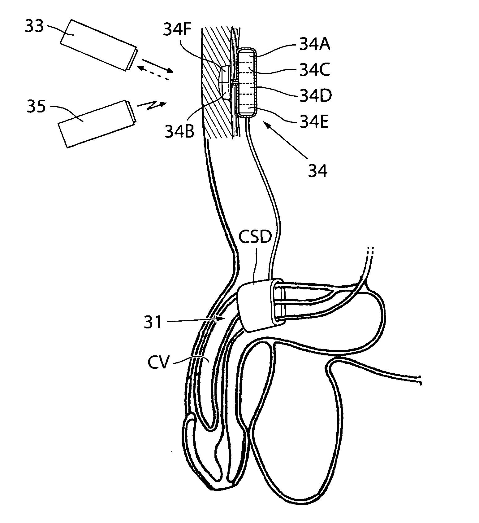
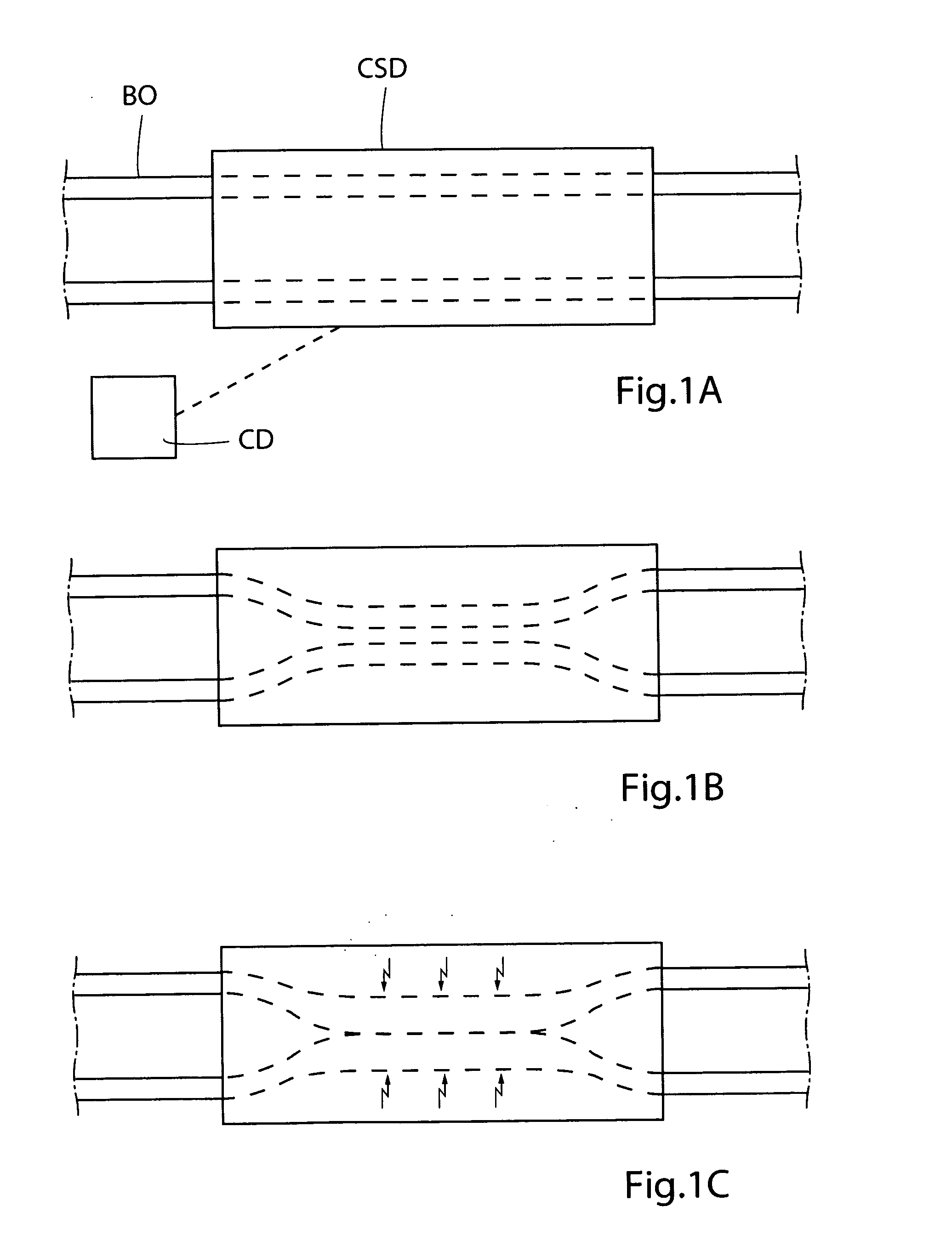
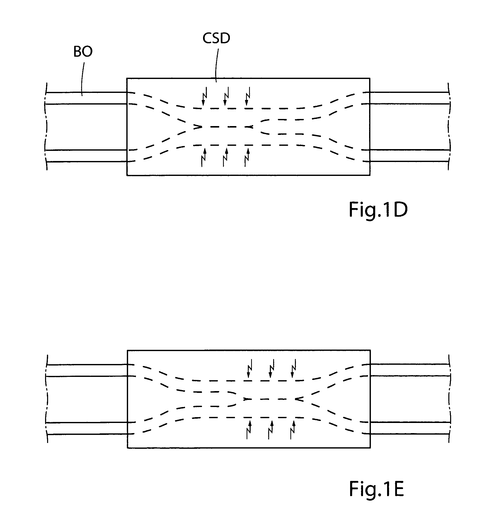
[0255]FIGS. 1A, 1B and 1C schematically illustrate different states of operation of a generally designed apparatus used for practicing the method of the present invention, when the apparatus is applied on a patient's penile portion designated BO. The apparatus includes a constriction device and a stimulation device, which are designated CSD, and a control device designated CD for controlling the constriction and stimulation devices CSD. FIG. 1A shows the apparatus in an inactivation state, in which the constriction device does not constrict the penile portion BO and the stimulation device does not stimulate the penile portion BO. FIG. 1B shows the apparatus in a constriction state, in which the control device CD controls the constriction device to gently constrict the penile portion of the penile portion BO to a constricted state, in which the ...


PUM


Abstract

There is provided a method for treating a male impotent patient comprising stimulating at least one portion of the patient's normal penile tissue or the prolongation thereof to at least restrict the blood flow leaving the penis to achieve erection. To improve the erection effect the method further comprises gently constricting the penile portion or the prolongation thereof to restrict the venous blood flow in the penile portion, and then stimulating the constricted penile portion to cause contraction of the penile portion to at least further restrict the blood flow leaving the penis to achieve erection.

Description

CROSS-REFERENCE TO RELATED APPLICATION[0001]This application claims the benefit of Provisional Application No. 60 / 960,716. filed Oct. 11, 2007, the entire contents of which are hereby incorporated herein by reference in this application.FIELD OF THE INVENTION[0002]The present invention relates to a method for treating a male impotent patient blood flow.BACKGROUND OF THE INVENTION[0003]Male sexual impotence is a widespread problem. Many different solutions to this problem have been tried. A main solution currently practised and disclosed in for instance U.S. Pat. Nos. 5,437,605 and 4,841,461 is to implant a hydraulic inflatable / contractible silicon prosthesis in the cavities of the corpora cavernosa of the patient's penis. In fluid connection with this prosthesis is a reservoir implanted in the scrotum. By manual pumping action the prosthesis is filled with fluid from the reservoir to effect erect condition or is emptied of fluid, which returns to the reservoir, to effect flaccid con...

Claims


Application Information

Patent Timeline
01 Oct 2009
Publication
US20090248109A1
IPC
A61N1/00; A61F5/00
CPC
A61M1/1068; A61N1/3605; A61N1/36514; A61M1/122; A61N1/36578; A61N1/403; A61N1/36564; A61N1/3787
Inventors
FORSELL, PETER