
Stable photo acoustic trace gas detector with optical power enhancement cavity

a photo acoustic trace and optical power enhancement technology, applied in the field of photo acoustic trace gas detectors, can solve the problems of increasing thermal energy, increasing the temperature and pressure inside the acoustic cell, and unable to measure exhaled levels at ppb concentrations using expensive and bulky equipment, and achieves the effect of simple design

Inactive Publication Date: 2009-10-08
KONINKLIJKE PHILIPS ELECTRONICS NV
View PDF11 Cites 26 Cited by
  • Summary
  • Abstract
  • Description
  • Claims
  • Application Information

AI Technical Summary

Benefits of technology

The invention is a photo acoustic trace gas detector that uses a crystal oscillator or a quartz tuning fork as the transducer. The detector has a simpler design and requires fewer components than previous detectors. The ratio of the light beam is modulated to generate light pulses with a high amplitude, which is proportional to the concentration of the trace gas. The detector does not require a chopper, but uses the intrinsic properties of the cavity to modulate the excitation power. The ratio modulation is performed around the resonance value, which is the ratio that maximizes the amplification in the cavity. The detector has a high sensitivity and can detect small amounts of trace gas. The method includes producing a light beam, transforming it into light pulses, amplifying the light in an optical cavity, and converting the sound waves into electrical signals.

Problems solved by technology

This excitation leads to an increase of the thermal energy, resulting in a local rise of the temperature and the pressure inside the acoustic cell.
Currently, exhaled NO levels at ppb concentrations can be only measured using expensive and bulky equipment based on chemiluminescence or optical absorption spectroscopy.
It is the challenge for these hand-held gas-analyzing devices to combine sufficient high sensitivity (ppb level) with small portable devices with a simple design and a high robustness.
Current photo acoustic trace gas detectors have the disadvantage that small form factor lasers (i.e. diode lasers) do not have sufficient laser power to reach the sensitivity required for trace gas detection.
However, the design of Rossi et al. is not easily scalable to a portable dimension, while preserving high robustness.

Method used


Image

  • Stable photo acoustic trace gas detector with optical power enhancement cavity
  • Stable photo acoustic trace gas detector with optical power enhancement cavity
  • Stable photo acoustic trace gas detector with optical power enhancement cavity

Examples


Embodiment Construction

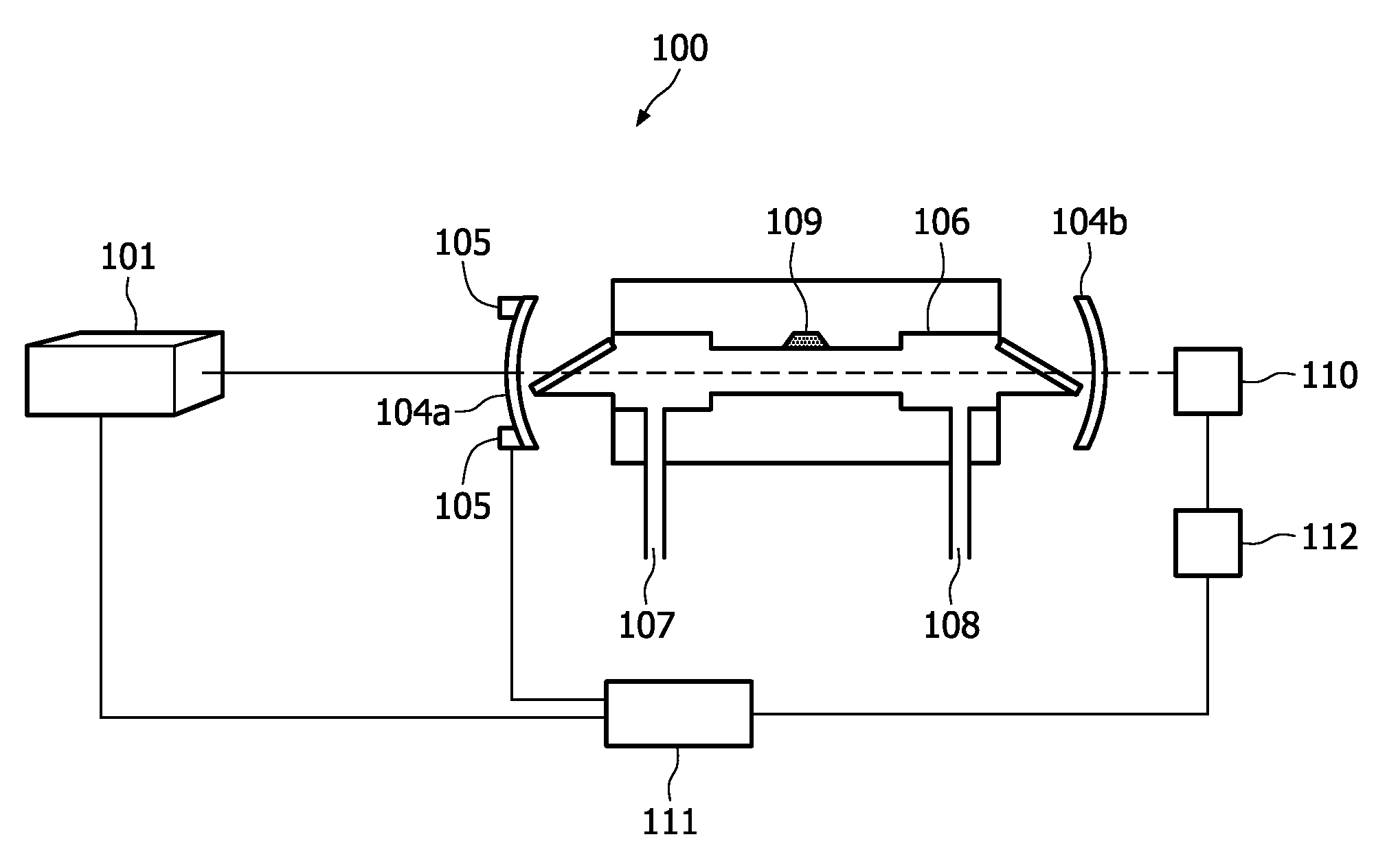
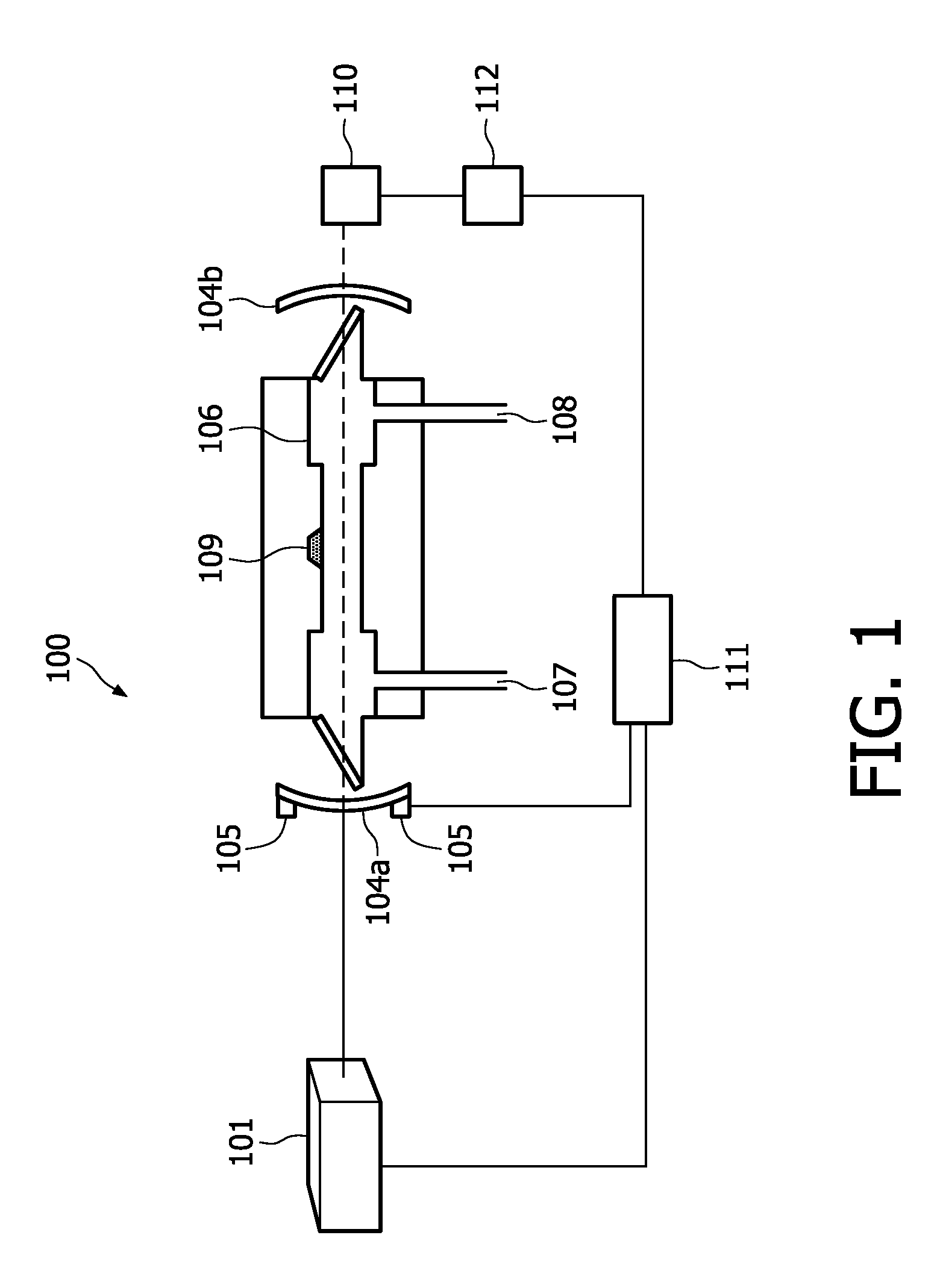
[0026]FIG. 1 shows a typical photo acoustic trace gas detector 100 according to the invention. A light source 101 provides a continuous wave light beam. Preferably, the light source 101 provides a laser beam. The light beam is sent into an optical cavity, which is defined by two semi-transparent mirrors 104a and 104b. The light beam enters the optical cavity through input mirror 104a and is reflected many times between the two cavity mirrors 104a and 104b. If the distance between the two mirrors 104a and 104b matches the wavelength of the laser, standing waves occur and the light intensity is amplified. An actuator, e.g. a piezo electric actuator 105, attached to one of the cavity mirrors 104a, 104b is used for modulating a length of the optical cavity. By modulation of the length of the optical cavity, the ratio of the laser wavelength and the cavity length is modulated. Maximum amplification of the light intensity is achieved at a resonance value for the ratio. Modulation electron...


PUM

PropertyMeasurementUnit
chopping frequencyaaaaaaaaaa
concentrationaaaaaaaaaa
lengthaaaaaaaaaa

Abstract

A photo acoustic trace gas detector (100) is provided for detecting a concentration of a trace gas in a gas mixture. The photo acoustic trace gas detector (100) comprises a light source (101), an optical cavity (104a, 104b), ratio modulating means (105, 111) and a transducer (109). The optical cavity (104a, 104b) contains the gas mixture and amplifies light intensity. Maximum amplification is provided when a ratio of a wavelength of the light beam and a length of the optical cavity (104a, 104b) has a resonance value. Ratio modulating means (105, 111) modulate the ratio for transformation of the light beam into a series of light pulses for generating the sound waves, an amplitude of the sound waves being a measure of the concentration of the trace gas. A transducer (109) converts the sound waves into electrical signals.

Description

TECHNICAL FIELD OF THE INVENTION[0001]The invention relates to a photo acoustic trace gas detector for detecting a concentration of a trace gas in a gas mixture, the photo acoustic trace gas detector comprising a light source for producing a light beam, an optical cavity for containing the gas mixture and for amplification of a light intensity of the light beam, the optical cavity providing a maximum amplification when a ratio of a wavelength of the light beam and a length of the optical cavity has a resonance value, ratio modulating means for modulating the ratio, and a transducer for converting sound waves in the gas mixture into electrical signals.BACKGROUND OF THE INVENTION[0002]Such a detector is known from the article “Optical enhancement of diode laser-photo acoustic trace gas detection by means of external Fabry-Perot cavity” by Rossi et al., published in Applied Physics Letters. The detector described therein sends a chopped laser beam through a gas contained in an acoustic...

Claims


Application Information

Patent Timeline
Patent Type & Authority Applications(United States)
IPC IPC(8): G01N21/00
CPCA61B5/0873G01N21/1702G01N29/2418G01N2291/021G01N2021/1704G01N2201/0221G01N33/497
Inventor VAN DIJK, ERIK MARTINUS HUBERTUS PETRUSKALKMAN, JEROEN
Owner KONINKLIJKE PHILIPS ELECTRONICS NV
Learn More