

Magneto-Optical Sensor
- Summary
- Abstract
- Description
- Claims
- Application Information
AI Technical Summary
Benefits of technology
Problems solved by technology
Method used
Image

Examples
first embodiment
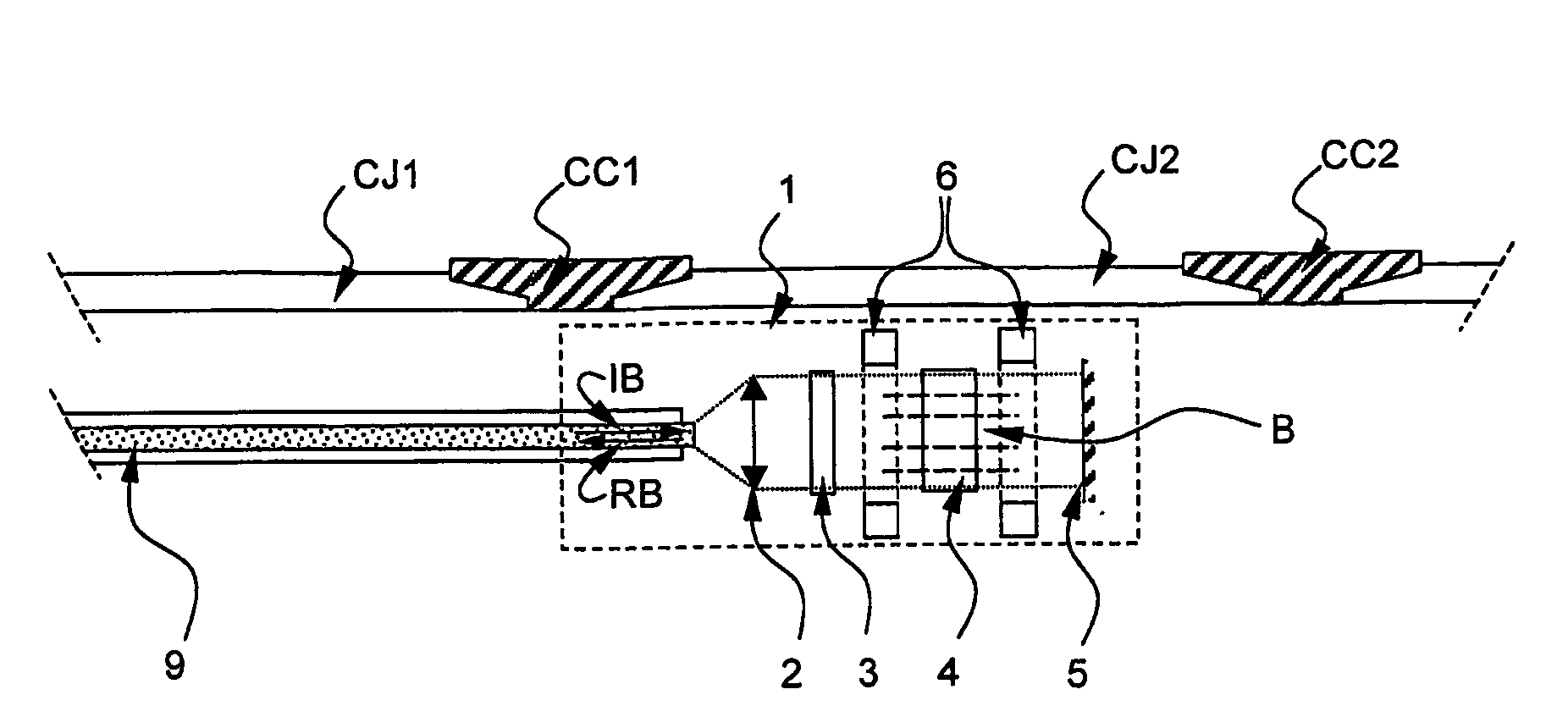
[0055]The magneto-optic sensor operates as follows. The incident beam IB provided by the optical fiber 9 is collimated through the beam shaping element 2. The incident beam IB travels through the polarizer 3, the resulting beam being linearly polarized. Subsequently, the incident beam IB travels through the Faraday rotator 4 which rotates the polarization of the beam.
[0056]According to FIG. 3.A, the magneto-optic sensor 1 is positioned along a casing joint CJ2 between two casing collars CC1, CC2. The Faraday rotator 4 provides a beam which polarization is rotated by an angle of rotation θ depending on the permanent magnetic field B applied on the Faraday rotator. The resulting beam is reflected on the reflective element 5 and travels a second time through the Faraday rotator 4 which once again rotates the polarization of the beam. The beam resulting from the double traveling through the Faraday rotator has a polarization state rotated by an angle of rotation 2θ. Then, said beam tra...
second embodiment
[0067]The magneto-optic sensor operates as follows. The incident beam IB provided by the first optical fiber 10 is shaped through the first beam shaping element 2. The incident beam IB travels through the polarizing element 3 and is linearly polarized. Subsequently, the incident beam IB travels through the Faraday rotator 4 which rotates the polarization of the incident beam IB. According to FIG. 4.A, the magneto-optic sensor 1′ is positioned along a casing joint CJ2 between two casing collars CC1, CC2. The Faraday rotator 4 provides a beam which polarization is rotated by an angle of rotation θ depending on the permanent magnetic field B applied on the Faraday rotator. Then, said beam travels through the analyzing element 7 which transmits only the polarization component corresponding to its polarization angle. The resulting response beam RB has an intensity Ir modified in correlation with the magnetic field applied on the Faraday rotator. The resulting response beam RB is shaped ...
third embodiment
[0081]The magneto-optic sensor operates as follows. The first IBA, second IBB, third IBC and fourth IBD incident beams respectively provided by the first 109A, second 109B, third 109C and fourth 109D optical fibers are respectively shaped through the beam shaping elements 102A, 102B, 102C, 102D. The first IBA, second IBB, third IBC and fourth IBD incident beams travel through the polarizing element 103 and are linearly polarized. Subsequently, the first IBA, second IBB, third IBC and fourth IBD incident beams travel through the Faraday rotator 104 which rotates the polarization of the first IBA, second IBB, third IBC and fourth IBD incident beams.
[0082]According to FIG. 5.A, the magneto-optic sensor 101 is positioned along a casing joint CJ3. The Faraday rotator 104 provides a plurality of beams which polarizations are rotated by an angle of rotation θ depending on the permanent magnetic field B applied on the Faraday rotator. Then, said beams are reflected on the reflective elemen...
PUM
 Abstract
Description
Claims
Application Information