Method for reducing interference

Active Publication Date: 2009-10-08
NOKIA TECHNOLOGLES OY
View PDF15 Cites 55 Cited by
  • Summary
  • Abstract
  • Description
  • Claims
  • Application Information

AI Technical Summary

Benefits of technology

[0055]The invention can also be provided as an integrated circuit, for example as a circuit having a processor unit and a memory means, or for example as a dedicated ASIC circuit. According to an eighth aspect of the invention, an integrated circuit for a mobile station of a wireless communication network is provided, the mobile station having a first transmitter, a first receiver, and at least a second receiver. The inte

Problems solved by technology

Combining different wireless technologies in a portable device such as a mobile phone or, more generally, a mobile station produces a number of problems.
One difficult problem is interference of different wireless systems combined in the same device.
For example, GSM transmissions can disturb WLAN connections, since harmonics of some GSM transmissions may in some cases fall within a WLAN frequency band.
This is a significant problem, when a WLAN receiver and a GSM transmitter are in close proximity, for example integrated in the same device such as a mobile phone.
Harmonics are a problem for example in a device transmitting on a frequency band near 850 MHz, and having a Bluetooth receiver.
Filtering can help remove the unwanted harmonics, but the filtering structures can be complicated and expensive.
Also, filtering in high frequency such as in the 5 GHz WLAN frequency band, it is technically difficult to build high quality filters.
However, the substrate material also causes loss of RF signal.
The 5 GHz WLAN band is troublesome for filtering also because of its wide bandwidth of 675 MHz, which complicates filter design.
In such a case, adding a filter to reduce interference of the transmitter to a second service would increase complexity and cost of the receiver.
Receiver and transmitter insertion losses will also increase when extra filtering is added.
This results in higher current consumption in transmitter and lower sensitivity in receiver.
Filtering is very difficult also in cases where a frequency band of a cellular communications network is very close to a frequency band of a second service.
The ba

Method used


Image

  • Method for reducing interference
  • Method for reducing interference
  • Method for reducing interference

Examples


Embodiment Construction

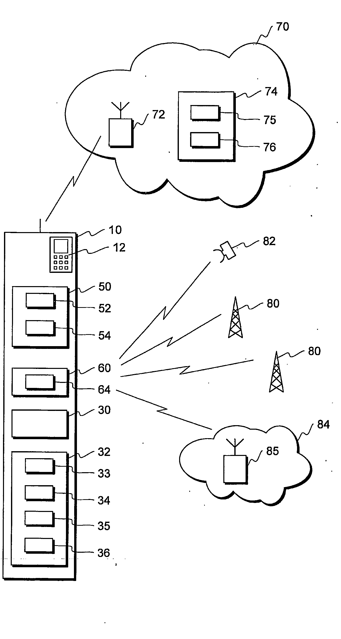
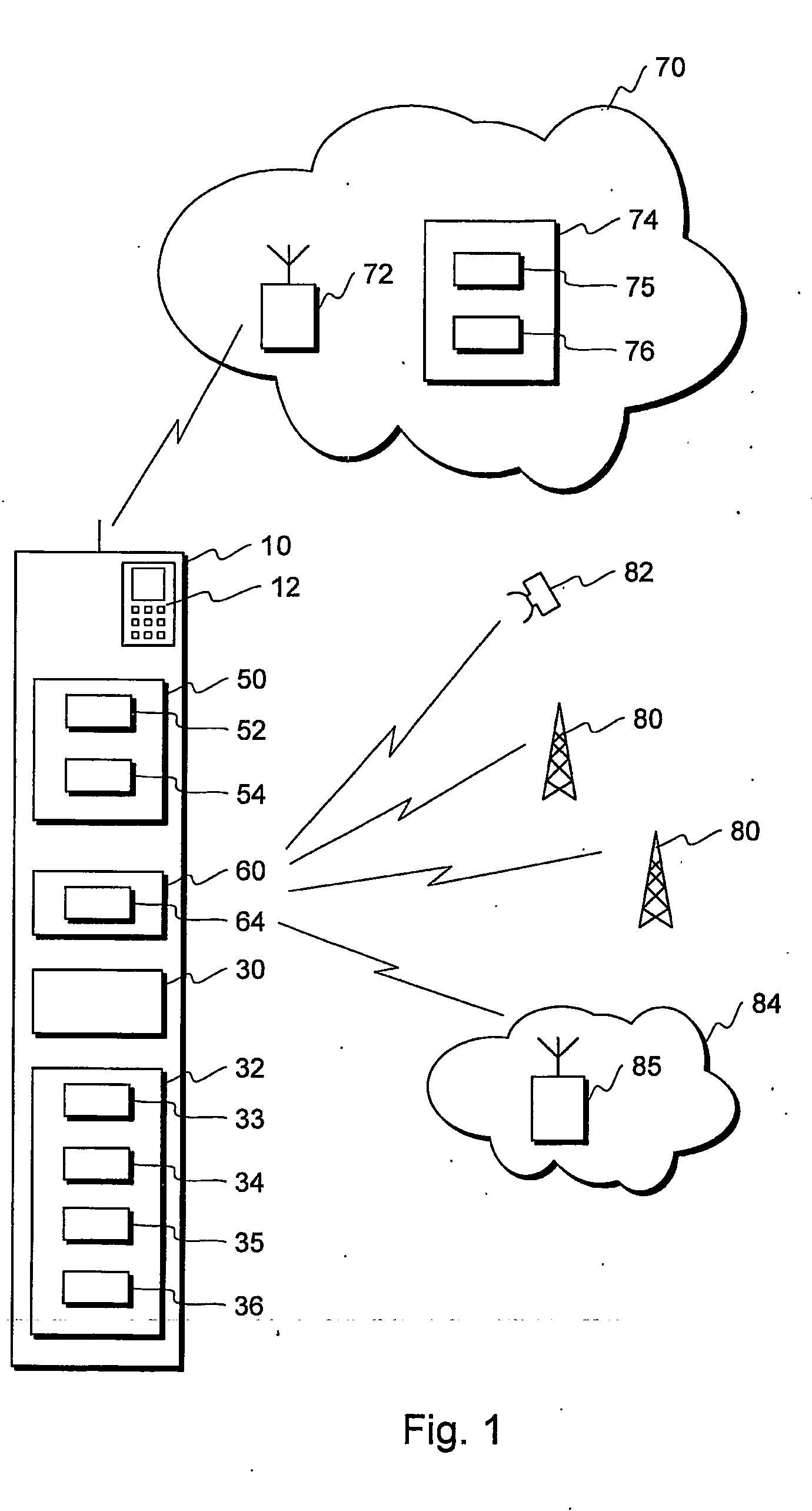
[0062]FIG. 1 illustrates a mobile station 10 comprising a first wireless part 50 with a first transmitter 52 and a first receiver 54, and a second wireless part 60 with at least a second receiver 64. The mobile station has also an user interface 12 comprising for example a display and a keyboard. The mobile station also comprises at least one processor 30 for controlling the operations of the mobile station and performing many of the functions of the mobile station. A mobile station typically comprises many other components as well, but for clarity, other components are not illustrated in FIG. 1.

[0063]FIG. 1 also illustrates a wireless communication network 70 having a base station 72, with which the mobile station 10 communicates. The wireless communication network can be for example a cellular communication network such as a GSM, UMTS, or a CDMA network, or a WLAN network.

[0064]FIG. 1 also illustrates several other types of wireless services that the second wireless part 60 of the...


PUM


Abstract

This invention relates to wireless communication systems, specifically to methods for reducing interference. The invention allows a mobile station to determine if certain transmissions of the mobile station cause interference to reception by a second receiver in the mobile station, and indicate to the network that a change in a transmission parameter of the mobile station is desired. The network can then change a transmission parameter to reduce interference observed by the second receiver.

Description

FIELD OF INVENTION[0001]This invention relates to wireless communication systems, specifically to methods for reducing interference.TECHNOLOGICAL BACKGROUND[0002]A communication system is a facility that enables communication between two or more entities such as user terminal equipment and / or network entities and other nodes associated with a communication system. The communication may comprise, for example, communication of voice, electronic mail (email), text messages, data, multimedia and so on.[0003]The communication may be provided by fixed line and / or wireless communication interfaces. A feature of wireless communication systems is that they provide mobility for the users thereof. An example of a communication system providing wireless communication is a public land mobile network (PLMN). An example of the fixed line system is a public switched telephone network (PSTN).[0004]A cellular telecommunication system is a communications system that is based on the use of radio access...

Claims


Application Information

Patent Timeline
IPC IPC(8): H04W40/36H04B15/00H04W36/06H04W36/20
CPCH04W36/20H04W36/06
Inventor LEINONEN, MARKOKANGAS, PERTTIROUSU, SEPPO
Owner NOKIA TECHNOLOGLES OY
Why Eureka
Try Eureka