
Retransmitting method and transmitting method in multi-antenna transmission

Inactive Publication Date: 2009-10-08
INVT SPE LLC
View PDF3 Cites 35 Cited by
  • Summary
  • Abstract
  • Description
  • Claims
  • Application Information

AI Technical Summary

Benefits of technology

[0019]According to the present invention, it is possible to provide a retransmission technique which can improve reliability of data transmission and the system throughput of the MIMO system, and adapts to multi-antenna transmission.

Problems solved by technology

However, the complexity of the maximum likelihood detection method exponentially increases according to the number of transmission antennas, and therefore there is a problem that implementation is difficult.
A ZF detector is capable of completely canceling interference between transmission antennas, but has a problem that background noise increases at the same time.
In the conventional mobile communication, there is a problem that radio channels are uncertain and likely to change due to a poor radio channel environment.
The MIMO system has the same problem.
However, the retransmitting method in the conventional HARQ technique adapts to a single antenna, and there is a problem that it is not possible to improve transmission reliability of the system and increase the system throughput by using the HARQ technique in a multi-antenna environment.

Method used


Image

  • Retransmitting method and transmitting method in multi-antenna transmission
  • Retransmitting method and transmitting method in multi-antenna transmission
  • Retransmitting method and transmitting method in multi-antenna transmission

Examples


embodiment 1

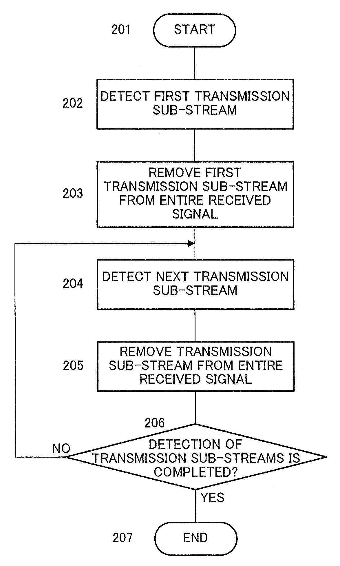
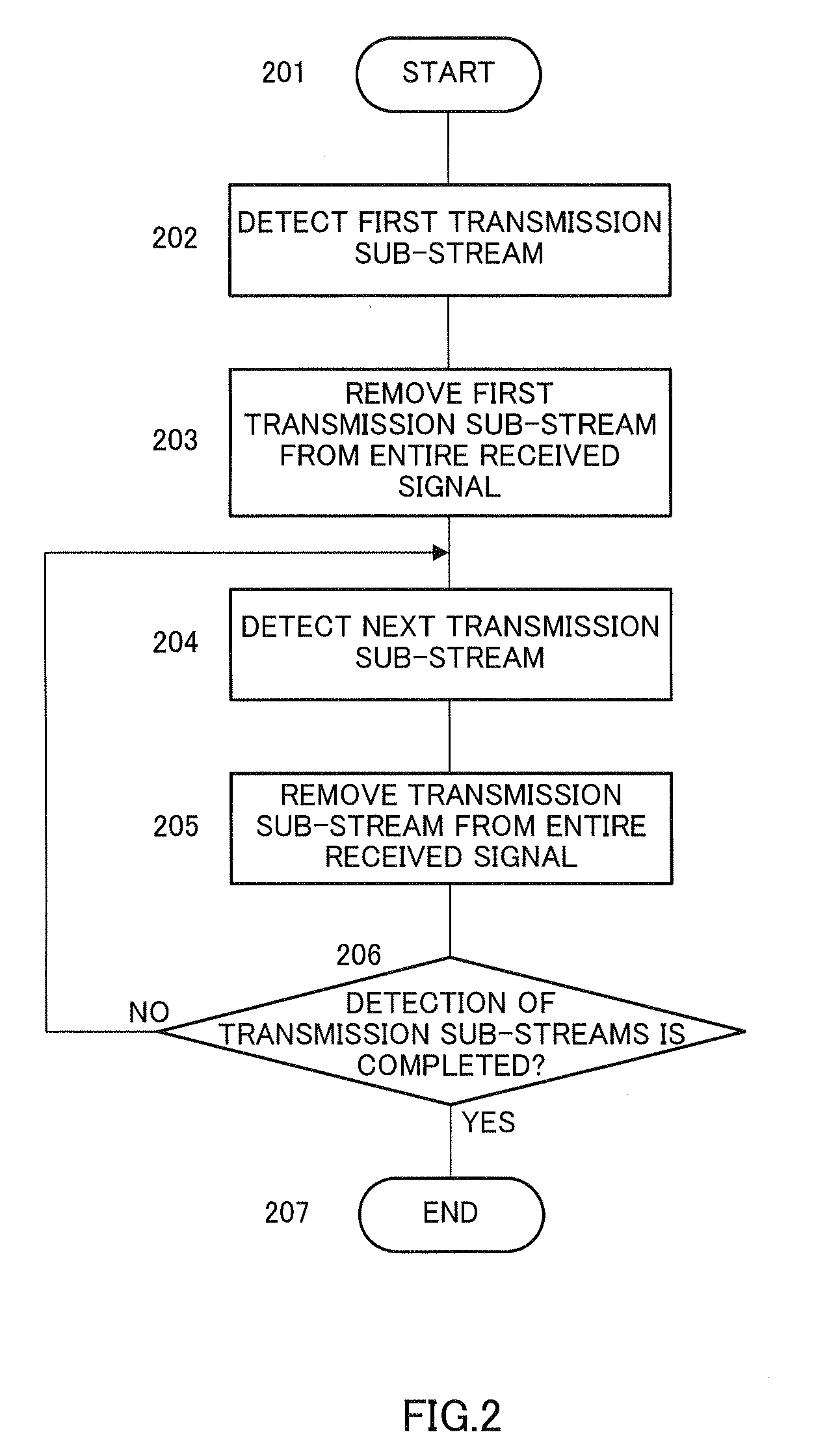
[0027]FIG. 2 is a flowchart illustrating an SIC detection method in Embodiment 1.

[0028]In step 201, detection starts. In step 202, based on current channel characteristic matrix H, a first transmission sub-stream is detected from the entire received signal using detector ZF or MMSE. When the sub-stream is detected, in step 203, the influence of the first transmission sub-stream is removed from the entire received signal.

[0029]Next, in step 204, in the received signal from which the transmission sub-stream is removed, the next transmission sub-stream is detected again using the detector. When the sub-stream is detected, in step 205, the influence of the transmission sub-stream is removed from the entire received signal. Then, in step 206, it is judged whether detection of transmission sub-streams is completed or not.

[0030]When it is judged that detection of sub-streams is not completed in step 206, the flow returns to step 204, and detection continues. Until the nTth sub-stream is de...

embodiment 2

[0046]FIG. 5 is a block diagram showing the MIMO system of the HARQ technique according to Embodiment 2 of the present invention. As shown in FIG. 5, the MIMO system of the HARQ technique according to Embodiment 2 removes data rearranging section 301, and has MIMO detection section 501 in place of MIMO detection section 307 in the MIMO system of the HARQ technique according to Embodiment 1 shown in FIG. 3. In addition, in FIG. 5, components that are the same as those in FIG. 3 will be assigned the same reference numerals without further explanations. Further, an SIC detection method in Embodiment 2 is the same as in FIG. 2, and descriptions thereof are omitted.

[0047]MIMO detection section 501 selects the detection order different from the detection order of last reception upon retransmission of a data sub-stream, and detects data sub-streams.

[0048]When the data has an error and detection is performed in the variable detection order on the receiving side, data which had an error is t...


PUM


Abstract

A transmitting apparatus capable of enhancing the certainty of data transmission of MIMO system, improving the system throughput, and providing a retransmission technique adaptive to the multi-antenna transmission. In this apparatus, a serial / parallel converting part (300) serial / parallel converts the data, which is to be transmitted, into a number nT of data substreams. A data rearranging part (301) rearranges, based on feedback information, the nT data substreams. CRC encoding parts (302) CRC encode the respective data substreams. Modulating / encoding parts (303) modulate and encode the respective corresponding data substreams. A number nT of transmission antennas (304) transmit the data substreams.

Description

TECHNICAL FIELD[0001]The present invention relates to a retransmitting method and a transmitting apparatus in multi-antenna transmission.BACKGROUND ART[0002]In the next-generation wireless communication system, demands for information rates and transmission quality have further increased. Conventionally, how to use resources in the time domain and the frequency domain has been mainly studied. In recent years, with the emergence of the multi-antenna (MIMO) technique, the new direction has been given to researchers. In the MIMO system, a transmitting side transmits signals using a plurality of antennas, while a receiving side receives the signals using a plurality of antennas. As compared with the conventional single-antenna transmission scheme, the MIMO technique is capable of remarkably increasing the channel capacity and further increasing the Information transmission rate. The spatial resource can be used almost endlessly as compared with the resources in the time domain and the f...

Claims


Application Information

Patent Timeline
IPC IPC(8): H04K1/10H04J99/00
CPCH04B7/061H04L1/0061H04L1/1887H04L1/1867H04L1/1812H04L1/18H04B7/08H04B7/06H04L1/16
Inventor LI, JIFENGYU, XIAOHONGSHE, XIAOMING
Owner INVT SPE LLC
Features
  • Generate Ideas
  • Intellectual Property
  • Life Sciences
  • Materials
  • Tech Scout
  • Unparalleled Data Quality
  • Higher Quality Content
  • 60% Fewer Hallucinations
Learn More