Method of repairing a fuel nozzle

Inactive Publication Date: 2009-10-15
GENERAL ELECTRIC CO
View PDF83 Cites 42 Cited by
  • Summary
  • Abstract
  • Description
  • Claims
  • Application Information

AI Technical Summary

Problems solved by technology

Because of limited fuel pressure availability and a wide range of required fuel flow, many fuel injectors include pilot and main nozzles, with only the pilot nozzles being used during start-up, and both nozzles being used during higher power operation.
Over time, continued exposure to high temperatures during turbine engine operations may induce thermal gradients and stresses in the conduits and fuel nozzle components which may damage the conduits or fuel nozzle components and may adversely affect the operation of the fuel nozzle.
For example, thermal gradients may cause fuel flow reductions in the conduits and may lead to excessive fuel maldistribution within the turbine engine.
Exposure of fuel flowing through the conduits and orifices in a fuel nozzle to high temperatures may lead to coking of the fuel and lead to blockages and non-uniform flow.
To provide low emissions, modern fuel nozzles require numerous, complicated internal air and fuel circuits to create multiple, separate flame zones.
Furthermore, over time, continued operation with damaged fuel nozzles may result in decreased turbine efficiency, turbine component distress, and/or reduced engine exhaust gas temperature margin.
Assembling and repairing such conventional fuel nozzles is time consuming, difficult and expensive.
Conventional gas turbine engine components such as, for example, fuel nozzles and their associated swirlers, conduits, distribution systems, venturis and mixing systems are generally expensive to fabricate and/or repair because the conventional fuel nozzle desig

Method used


Image

  • Method of repairing a fuel nozzle
  • Method of repairing a fuel nozzle
  • Method of repairing a fuel nozzle

Examples


Embodiment Construction

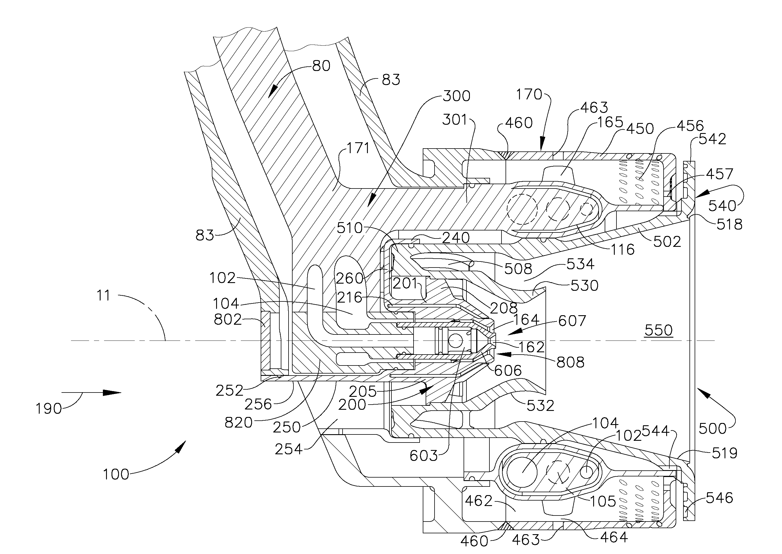
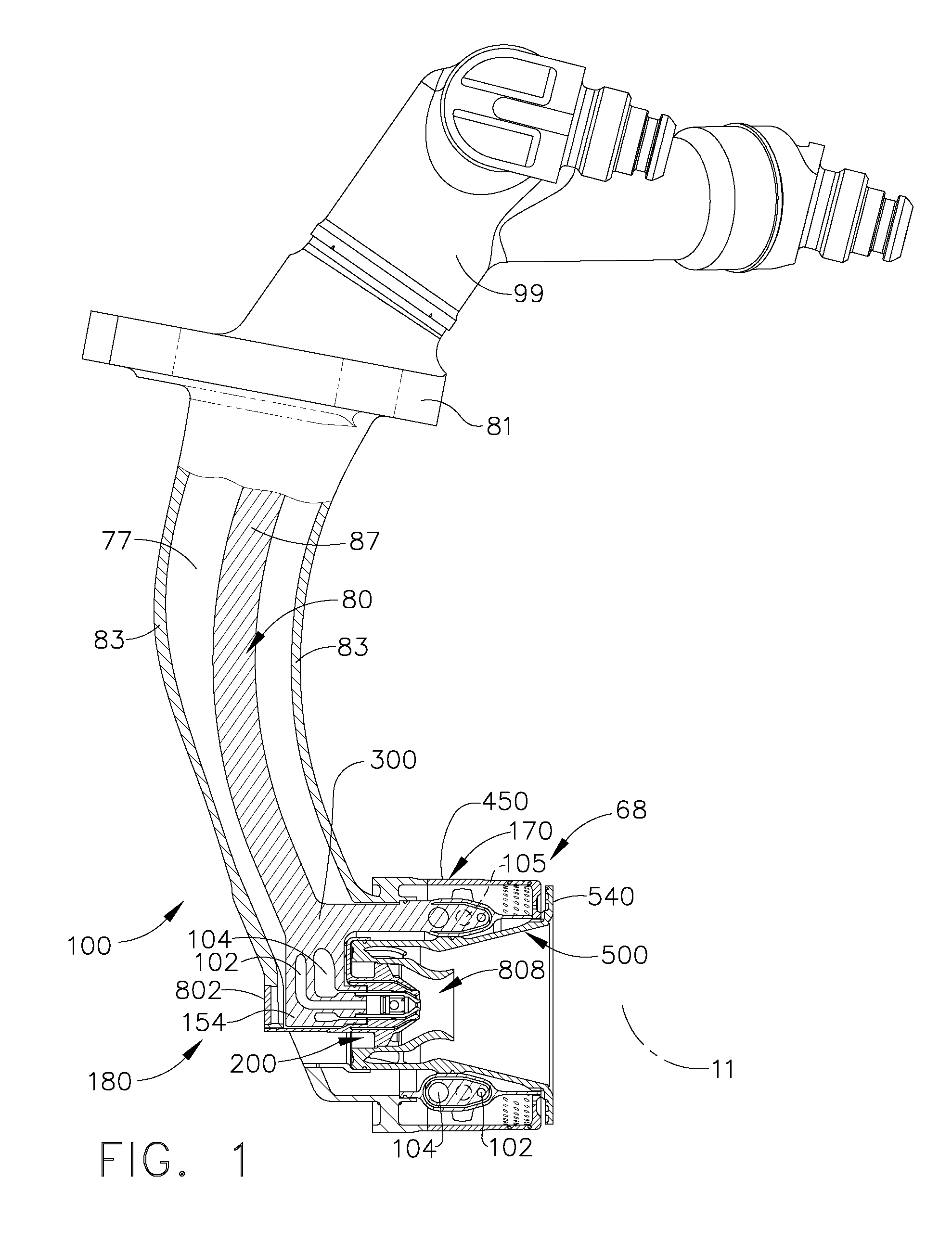
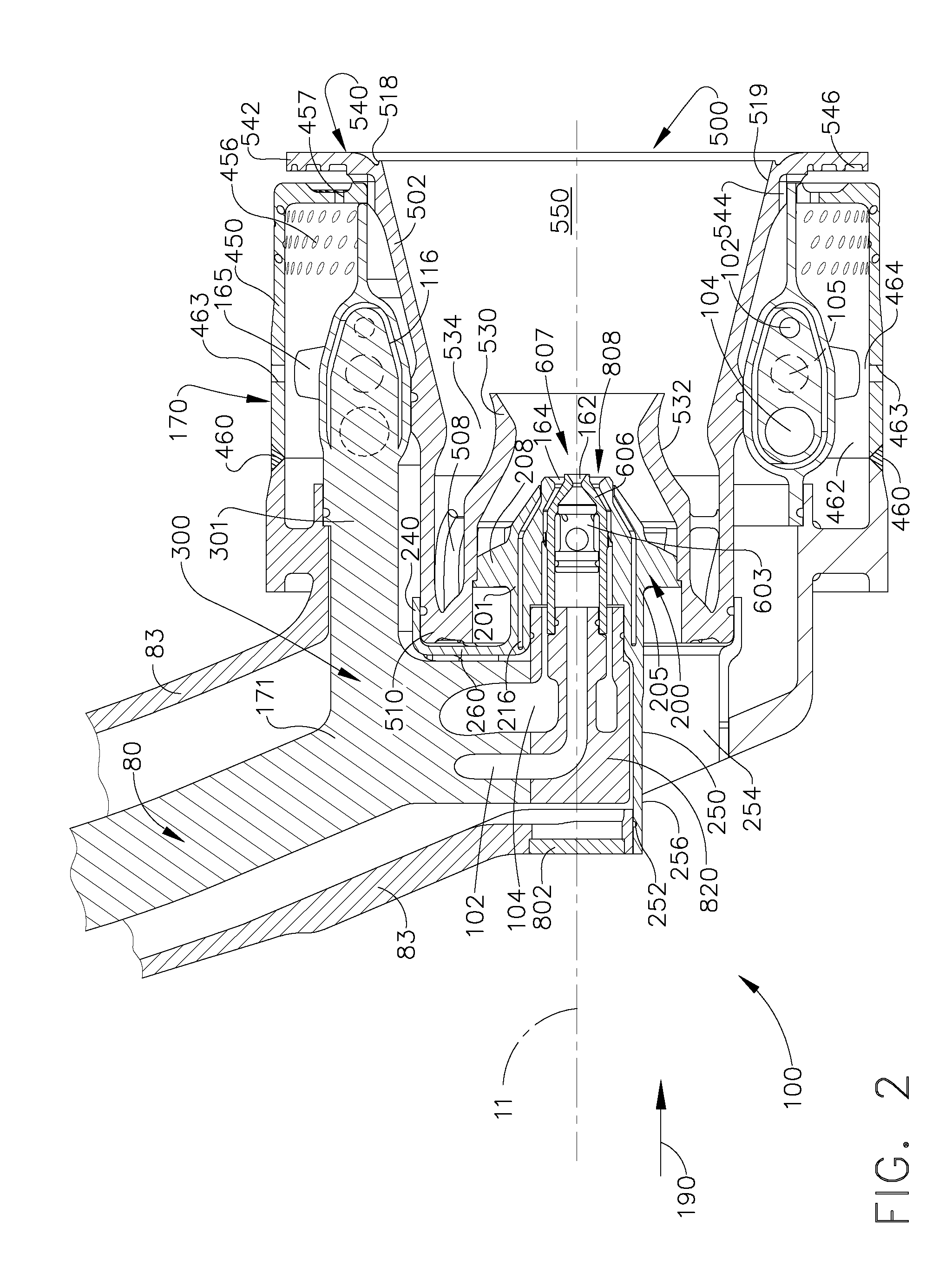
[0031]A gas turbine engine has a combustion chamber housed within an engine outer casing. Fuel is supplied into the combustion chamber by fuel nozzles, such as for example shown in FIGS. 1 and 2. Liquid fuel is transported through conduits 80 within a stem 83, such as, for example, shown in FIG. 1, to the fuel nozzle tip assembly 68. Conduits that have a unitary construction may be used for transporting the liquid fuel into the fuel nozzle tip assembly 68 of the fuel nozzles. The fuel supply conduits, may be located within the stem 83 and coupled to a fuel distributor tip 180. Pilot fuel and main fuel are sprayed into the combustor by fuel nozzle tip assemblies 68, such as for example, shown in FIGS. 1 and 2. During operation of the turbine engine, initially, pilot fuel is supplied through a pilot fuel flow passage, such as, for example, shown as items 102, 104 in FIG. 2, during pre-determined engine operation conditions, such as during startup and idle operations. The pilot fuel is...


PUM


Abstract

A method of repairing a fuel nozzle is disclosed comprising the steps of forming a pilot assembly; installing into a repair bore; inserting a primary adaptor into a repair bore such that the primary adaptor is in flow communication with a pilot flow passage and the pilot assembly; and coupling the primary adaptor to a distributor and the new pilot assembly.

Description

CROSS-REFERENCE TO RELATED APPLICATIONS[0001]This Application claims priority to U.S. Provisional Application Ser. No. 61 / 044,116, filed Apr. 11, 2008, which is herein incorporated by reference in its entirety.BACKGROUND OF THE INVENTION[0002]This invention relates generally to fuel nozzles used in gas turbine engines, and more specifically to repairable fuel nozzles, components and methods of repairing fuel nozzle components and assemblies.[0003]Turbine engines typically include a plurality of fuel nozzles for supplying fuel to the combustor in the engine. The fuel is introduced at the front end of a burner in a highly atomized spray from a fuel nozzle. Compressed air flows around the fuel nozzle and mixes with the fuel to form a fuel-air mixture, which is ignited by the burner. Because of limited fuel pressure availability and a wide range of required fuel flow, many fuel injectors include pilot and main nozzles, with only the pilot nozzles being used during start-up, and both noz...

Claims


Application Information

Patent Timeline
IPC IPC(8): B23P6/00B23P15/04
CPCB23P6/007Y10T29/49318F23D2900/00018F23D2900/14701F23R3/14F23R3/283F23R3/286F23R3/343F23R2900/00018Y02T50/675B22F2007/068B23P6/005Y10T29/49746Y10T29/4932B23P2700/13F23D2213/00F23R3/28Y10T137/265B33Y80/00Y02P10/25Y02E30/30F23C7/004F02C7/222B23P6/00F23D11/38Y02T50/60
Inventor MCMASTERS, MARIE ANNBENJAMIN, MICHAEL A.MANCINI, ALFRED
Owner GENERAL ELECTRIC CO
Why Eureka
Try Eureka