Power steering system, speed reduction mechanism and bearing holder

a technology of speed reduction mechanism and power steering system, which is applied in the direction of elastic bearings, bearing units, rigid supports of bearings, etc., can solve the problems of reduced productivity, increased manufacturing costs, and difficulty in ensuring sufficient machining accuracy, so as to enhance the ability of the peripheral wall to hold bearings, reduce bearing pressure, and increase the area of peripheral walls.

Inactive Publication Date: 2009-10-15
HITACHI LTD
View PDF7 Cites 31 Cited by
  • Summary
  • Abstract
  • Description
  • Claims
  • Application Information

AI Technical Summary

Benefits of technology

[0049]According to the above-mentioned invention, the interval of the slits at the basal-end side of the preload portion is set to a small value and the interval of the slits at the free-end side of the preload portion, that is, the interval of the slits at the outermost-end side of the preload portion, is set to a large value. Thus, it is possible to enlarge the area of the peripheral wall of the preload portion, while ensuring an appropriate preload created by the preload portion. By virtue of the enlarged area, it is possible to reduce a bearing pressure or a bearing stress acting on the peripheral wall of the preload portion and arising from an excessive input load transmitted from the worm wheel to the wormshaft. Therefore, even when the peripheral wall of the preload portion is jammed between the bearing and the inner wall of the holder housing portion with the input load, there is no risk of causing any damage to the peripheral wall of the preload portion. Furthermore, it is possible to enhance the peripheral-wall's ability to hold the bearing by enlarging the area of the preload portion, thus enabling the bearing to be certainly held at the central side of the bearing holder. As a result of this, it is possible to enhance the accuracy of meshed-engagement between the toothed portion of the wormshaft and the toothed portion of the worm wheel.

Problems solved by technology

Therefore, the system has difficulty in ensuring the sufficient machining accuracy.
The complicated machining of the eccentric groove leads to the problem of reduced productivity, thus resulting in higher manufacturing costs.
As set forth above, the system has difficulty in ensuring a sufficient machining accuracy of the groove, thus resulting in individual differences of elastic forces produced by O rings installed in place.
As a result, it is difficult to create a desired elastic force.
This leads to the technical problem of the difficulty of achieving high-precision meshed-engagement between the toothed portion of the worm wheel and the toothed portion of the wormshaft.

Method used


Image

  • Power steering system, speed reduction mechanism and bearing holder
  • Power steering system, speed reduction mechanism and bearing holder
  • Power steering system, speed reduction mechanism and bearing holder

Examples


first embodiment

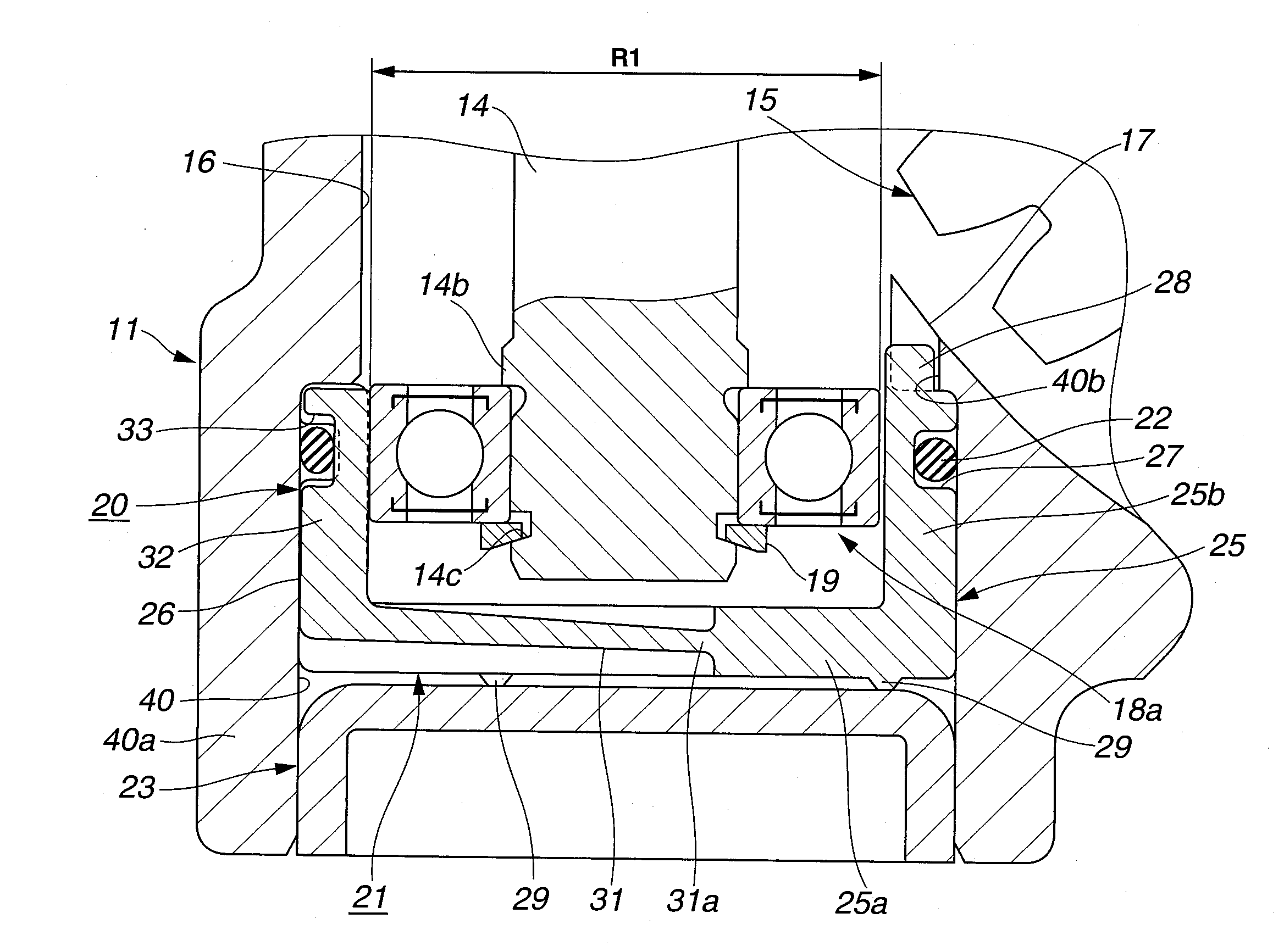
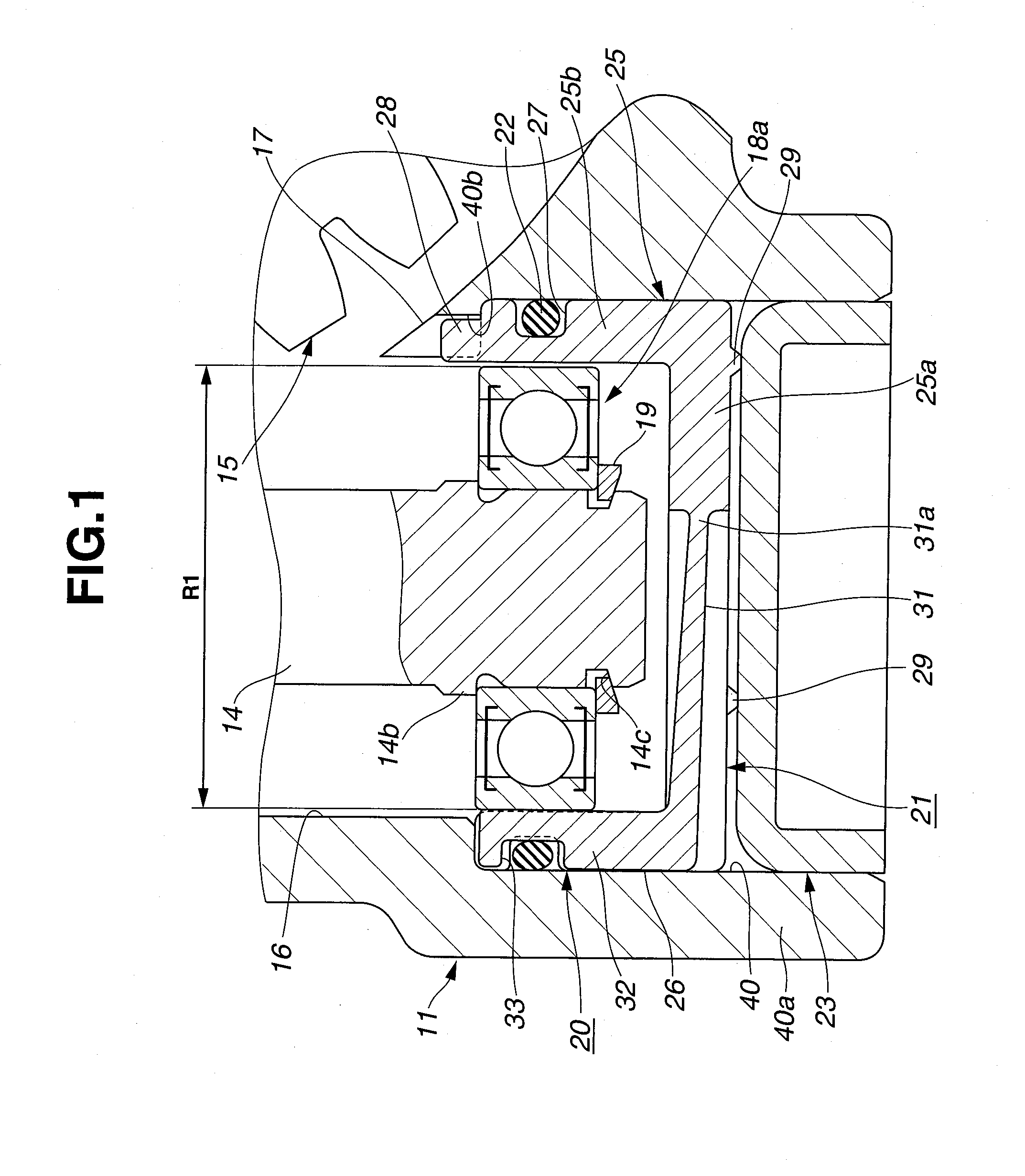
[0051]FIGS. 1-13 show the power steering system and its configuration of the first embodiment, made according to the invention. As shown in FIG. 13, the power steering system 1 is provided with a steering shaft 3 connected to a steering wheel 2, an input shaft 4 linked to steering shaft 3, an output shaft 5, which is formed at its top end with a pinion gear and arranged coaxially with input shaft 4 and linked through a torsion bar (not shaft) to the input shaft so that relative rotation of the output shaft to the input shaft is permitted, a rack shaft 6 having a rack gear formed over a given length in the axial direction of the rack shaft and adapted to mesh with the pinion gear of output shaft 5, and tie rods 7, 7 adapted to link both ends of rack shaft 6 and steering knuckles (not shown) linked to respective road wheels WL, WR.

[0052]As is generally known, when steering wheel 2 is turned, input shaft 4 rotates synchronously with rotary motion of steering shaft 3 and thus the torsio...

second embodiment

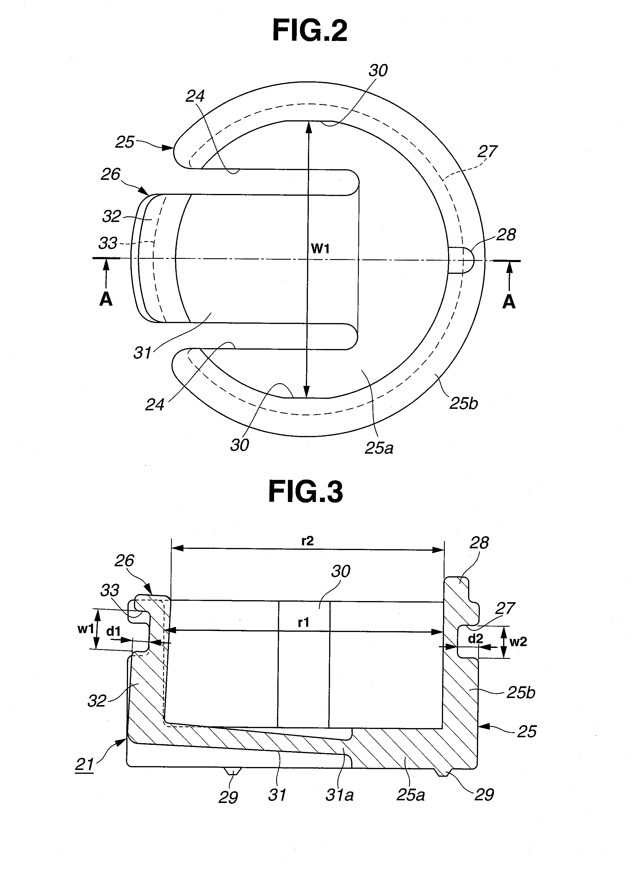
[0091]FIGS. 14-15 show the system of the second embodiment, made according to the present invention, which modifies preloading means, constructing preload portion 26. Preload portion 26 is configured such that, under an unloaded condition, its pushing portion 32 is arranged substantially parallel to the peripheral wall 25b of holding portion 25, and that the inside diameter r2 of the inside edged portion of pushing portion 32 is dimensioned to be substantially identical to the inside diameter r1 of holding portion 25, thus forcing preload portion 26 radially inward by only the shrinkage force of O ring 22. That is, by fitting O ring 22 into second annular groove 33, whose depth is formed to be shallower than that of first annular groove 27, as indicated by the two-dotted line in the drawings, by virtue of a shrinking action of O ring 22, preload portion 26 is kept in a state where the preload portion is pulled inward.

[0092]Therefore, the second embodiment can provide the same operat...

eighth embodiment

[0103]Additionally, in the eighth embodiment, plug member 23 is eliminated. In lieu thereof, as shown in FIG. 27, the lower end of adjustment-mechanism housing portion 40 is closed by a bottom wall 40c, which is formed integral with its peripheral wall (the previously-discussed restriction wall 40a). Furthermore, adjustment-mechanism housing portion 40 is formed to have almost the same bore as shaft housing portion 16, and therefore the stepped portion between shaft housing portion 16 and adjustment-mechanism housing portion 40 is eliminated. Hence, the upper wall portion of adjustment-mechanism housing portion 40 is also eliminated.

[0104]Regarding bearing holder 21, as shown in FIGS. 25 to 27, owing to the elimination of the upper wall portion of adjustment-mechanism housing portion 40, the location of engaged protrusion portion 28 of holding portion 25 is modified. That is, the engaged protrusion portion is formed on the lower end face, i.e., on the outer bottom surface of bottom ...


PUM


Abstract

[PROBLEMS] The object of the invention to provide a power steering system capable of ensuring a sufficient accuracy of meshed-engagement between toothed portions of a worm gear without complicated machining to be made to an inside of a housing.
[MEANS FOR SOLVING PROBLEMS] In a power steering system comprising a wormshaft (14), which is housed in a shaft housing portion (16) formed in a housing (11) and whose one end is rotatably supported by a first bearing (18a), a worm wheel (15) adapted to mesh with the wormshaft, a bottomed, substantially cylindrical bearing holder (21) configured to enclose and fit onto the first bearing for holding the first bearing, and a preloading means located in the bearing holder for preloading the first bearing in a direction of meshed-engagement of the worm gear, an adjustment-mechanism housing portion (40) is formed at one end of the shaft housing portion for housing and retaining the bearing holder, and a restriction wall (40a) is formed in the adjustment-mechanism housing portion (40) and arranged coaxially with the shaft housing portion for restricting a movement of the bearing holder at least in an opposite direction, which is opposite to the direction of meshed-engagement of the worm gear, and in a direction perpendicular to the opposite direction.

Description

TECHNICAL FIELD[0001]The present invention relates to an electric power steering system for an automotive vehicle, and specifically to an electric power steering system configured to be able to adjust a backlash between meshing gears installed in a speed reduction mechanism, mainly constructed by a worm gear, which gear can be applied to the power steering system.BACKGROUND ART[0002]For instance, an electric power steering system, which employs a speed reduction mechanism comprised of a worm wheel provided on the outer periphery of a steering shaft and a wormshaft, which is in meshed-engagement with the worm wheel and whose one axial end is connected to an electric motor, is well known as a typical power steering system. The electric power steering system is configured to assist a steering force by a driving force, produced by the electric motor and transmitted through the speed reduction mechanism, in response to a measure of torque in the steering shaft.[0003]In such an electric p...

Claims


Application Information

Patent Timeline
Patent Type & Authority Applications(United States)
IPC IPC(8): B62D5/04F16C27/00
CPCB62D5/0409F16H1/16F16H57/022F16H2057/0213F16H2057/127H02K7/081F16H2057/0222F16H55/24
Inventor KONDO, YOSHIMORISHIINO, KOHTARO
Owner HITACHI LTD
Why Eureka
Try Eureka