Plasma processing apparatus, plasma processing method, and tray

Active Publication Date: 2009-10-15
PANASONIC INTELLECTUAL PROPERTY MANAGEMENT CO LTD
View PDF8 Cites 370 Cited by
  • Summary
  • Abstract
  • Description
  • Claims
  • Application Information

AI Technical Summary

Benefits of technology

[0017]According to the present invention, the substrate is placed directly on the substrate placement surface and electrostatically attracted without interposition of the tray. This therefore allows the substrate to be retained on the substrate placement surface with high degree of adhesion, the cooling efficiency of the substrate to be improved, and the substrate temperature to be controlled with high accuracy. Further, a member of a clamp ring or the like for mechanically pressurizing the outer peripheral edge

Problems solved by technology

Therefore, the substrate cannot be efficiently cooled.
On the other hand, in the plasma processing apparatus disclosed in the latter publication, the state of the plasma tends to become unstable particularly at the vicinity of the outer peripheral edge of the substrate where the clamp ring exists.
This results in that the processing cannot be uniformed at a center portion and the vicinity o

Method used


Image

  • Plasma processing apparatus, plasma processing method, and tray
  • Plasma processing apparatus, plasma processing method, and tray
  • Plasma processing apparatus, plasma processing method, and tray

Examples


first embodiment

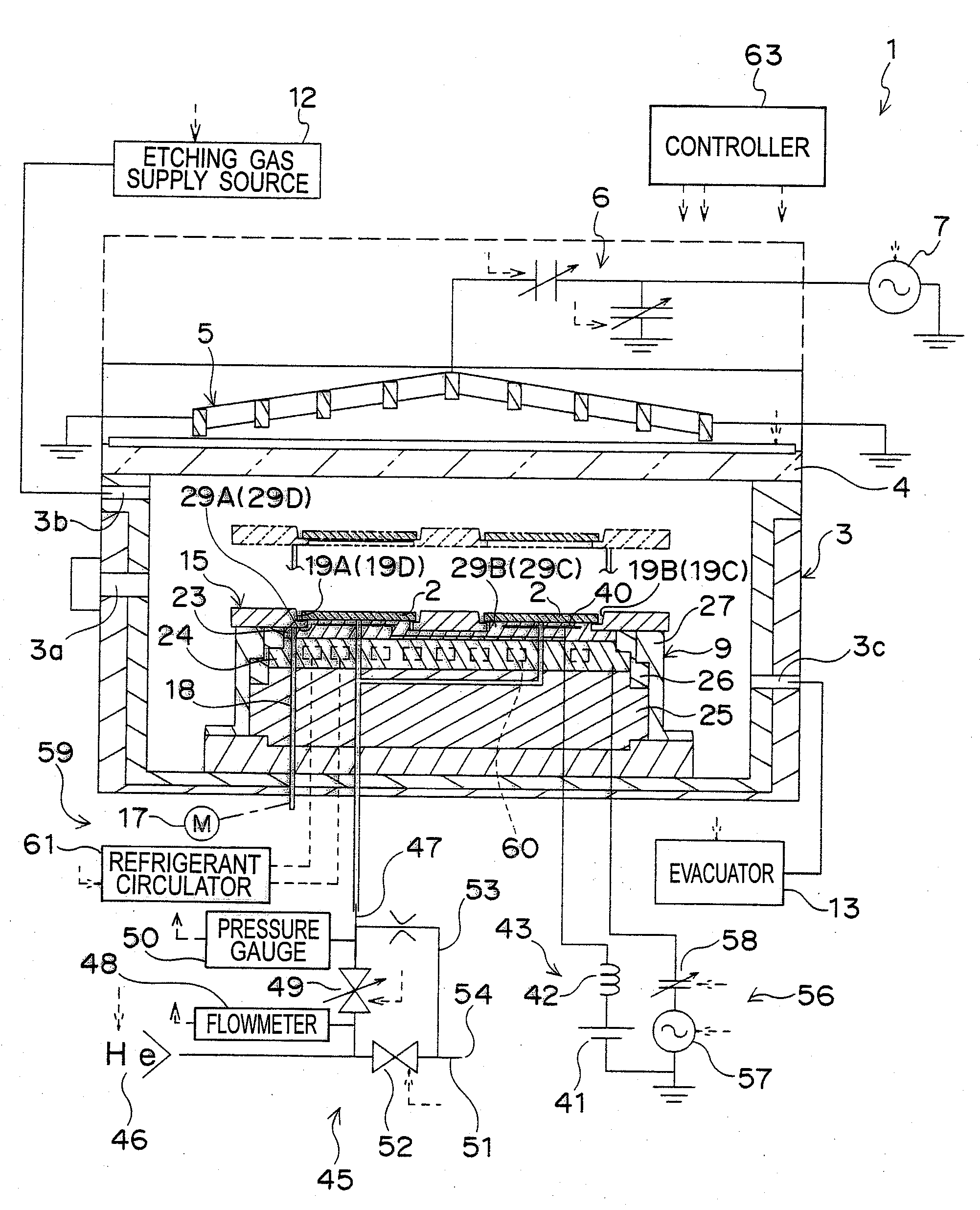
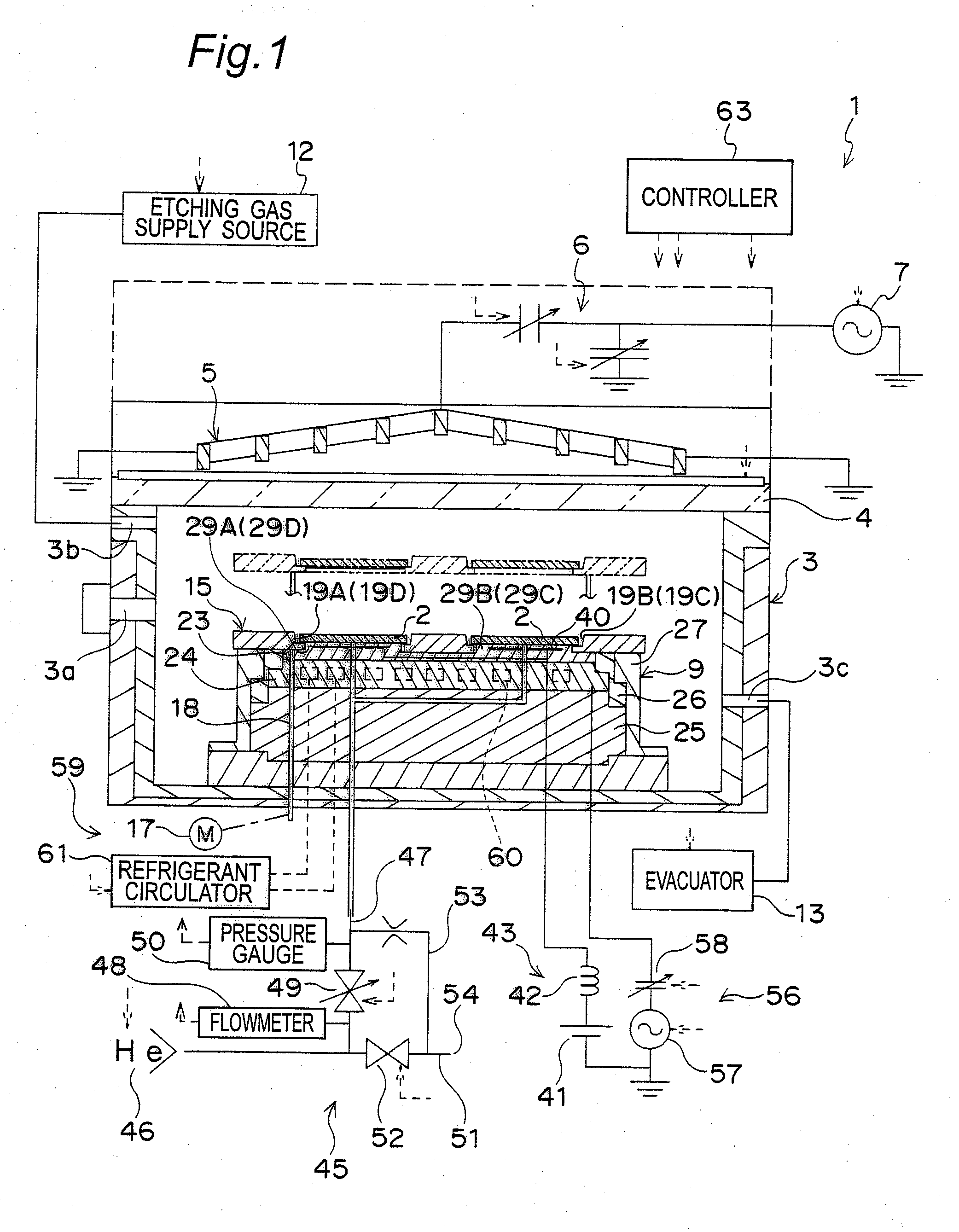
[0056]FIGS. 1 and 2 show a dry etching apparatus 1 of ICP (Induction Coupling Plasma) type according to a first embodiment of the present invention.

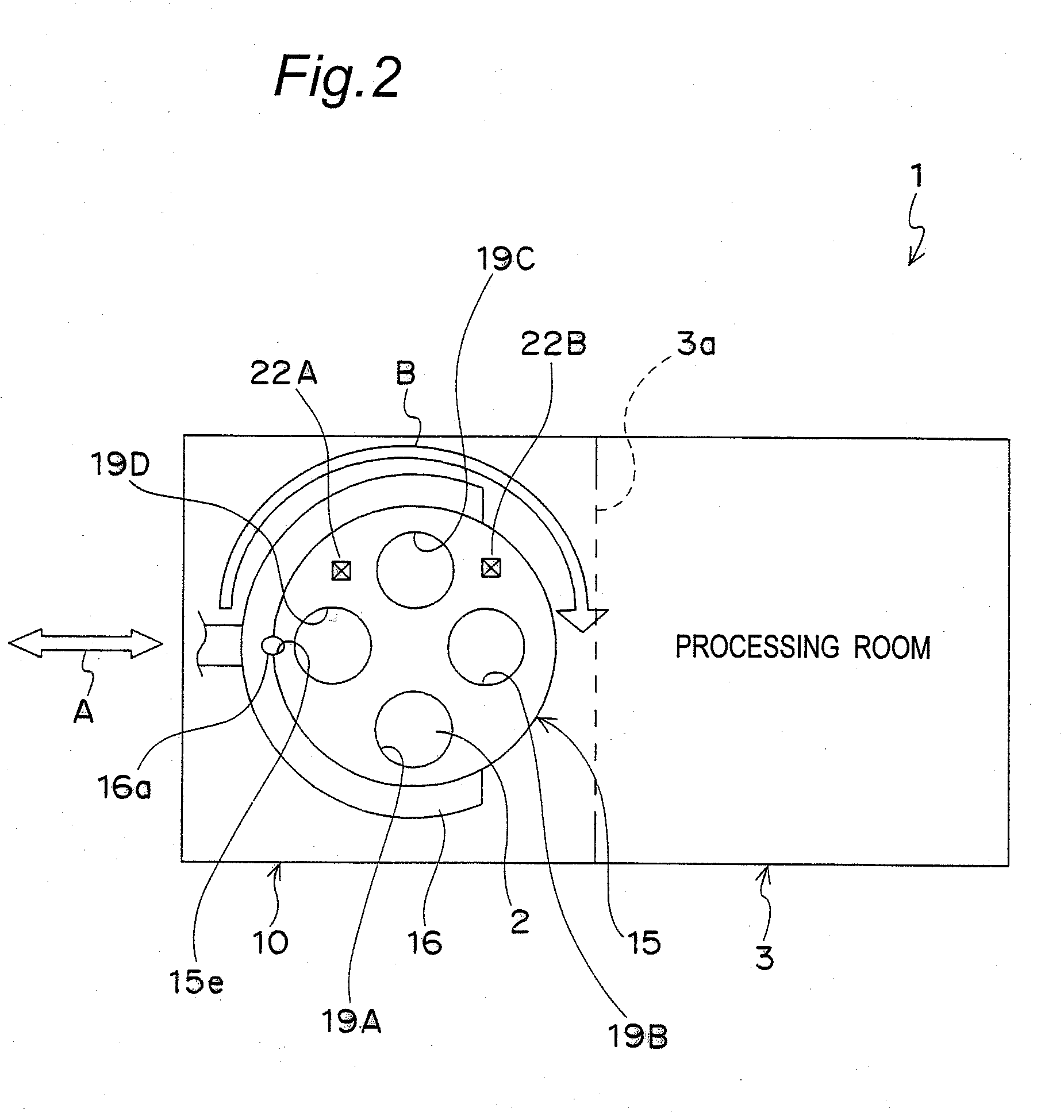
[0057]The dry etching apparatus 1 has a chamber (vacuum vessel) 3 that constitutes a processing chamber in which a substrate 2 is subjected to plasma processing. The chamber 3 has an upper end opening closed in a sealed state with a top plate 4 made of a dielectric substance of quartz or the like. An ICP coil 5 is arranged above the top plate 4. A high-frequency power source 7 is electrically connected to the ICP coil 5 via a matching circuit 6. Provided in a bottom side of in the chamber so as to be opposed to the top plate 4 is a substrate susceptor 9 that has a function as a lower electrode to which a bias voltage is applied and a function as a retainer of the substrate 2. The chamber 3 has an operable gate 3a for loading and unloading which communicates with an adjacent load dock chamber 10 (see FIG. 2). Further, an etching gas suppl...

second embodiment

[0093]A second embodiment of the present invention shown in FIGS. 11 through 13B differs from the first embodiment in the structures of the tray 15 and the dielectric plate 23 of the substrate susceptor 9.

[0094]Four projecting substrate support portions 21 are provided at intervals in the circumferential direction on the lower surface 15c side of the hole wall 15d of each of the substrate accommodation holes 19A through 19D formed in the tray main body 15a. Specifically, the four substrate support portions 21 are provided at equiangular intervals (intervals of 90°) with respect to the center of the substrate accommodation holes 19A through 19D when viewed from the direction of penetration of the substrate accommodation holes 19A through 19D. On the other hand, four receiving grooves 65 that extend from the substrate placement surface 31 toward the tray support surface 28 are formed on the outer peripheral surface 38 of each of the substrate placement portions 29A through 29D of the ...

third embodiment

[0098]The third embodiment of the present invention shown in FIG. 16 has an annular guide plate 67 for positioning the tray 15 to the dielectric plate 23. The guide plate 67 is fixed to the upper surface of the guide cylinder body 26 and surrounds the four substrate placement portions 29A through 29D of the dielectric plate 23. An inner peripheral surface 67a of the guide plate 67 is a tapered surface that expands from a lower surface 67b toward an upper surface 67c. Further, the thickness of the guide plate 67 is set approximately equal to the thickness of the tray 15.

[0099]With reference also to FIG. 17, according to the present embodiment, an outer peripheral surface 15f of the tray 15 is a tapered surface of which outside diameter is enlarged from the lower surface 15c toward the upper surface 15b. The dimensions and shapes including the taper degrees of the inner peripheral surface 67a of the guide plate 67 and the outer peripheral surface 15f of the tray 15 are set so that the...


PUM

PropertyMeasurementUnit
Currentaaaaaaaaaa
Currentaaaaaaaaaa
Electric dipole momentaaaaaaaaaa

Abstract

A tray 15 for a dry etching apparatus 1 has substrate accommodation holes 19A to 19D penetrating thickness direction and a substrate support portion 21 supporting an outer peripheral edge portion of a lower surface 2a of a substrate 2. A dielectric plate 23 has a tray support surface 28 supporting a lower surface of the tray 15, substrate placement portions 29A through 29D inserted from a lower surface side of the tray 15 into the substrate accommodation holes 19A through 19D and having a substrate placement surface 31 at its upper end surface for placing the substrate 2. A dc voltage applying mechanism 43 applies a dc voltage to an electrostatic attraction electrode 40. A heat conduction gas supply mechanism 45 supplies a heat conduction gas between the substrate 2 and substrate placement surface 31. The substrate 2 can be retained on the substrate placement surface 31 with high degree of adhesion. This results in that the cooling efficiency of the substrate 2 is improved and processing is uniformed at the entire region of the substrate surface including the vicinity of the outer peripheral edge.

Description

TECHNICAL FIELD[0001]The present invention relates to a plasma processing apparatuses, such as a dry etching apparatus and CVD apparatus, a plasma processing method and a tray for the plasma processing apparatus.BACKGROUND ART[0002]JP 2000-58514 A discloses plasma processing apparatus of a construction such that a bottomed tray accommodating a substrate is placed on a substrate susceptor that functions as a lower electrode. The substrate is electrostatically attracted to the substrate susceptor indirectly via the tray. A cooling mechanism is provided for the substrate susceptor, and the substrate is cooled by indirect heat conduction to the substrate susceptor via the tray.[0003]JP 2003-197607 A discloses a plasma processing apparatus of a construction such that a bottomed tray accommodating a substrate is placed on a substrate susceptor with a vicinity of an outer peripheral edge of the substrate being pressurized against the substrate susceptor side by a clamp ring, whereby the su...

Claims


Application Information

Patent Timeline
IPC IPC(8): H01L21/306C23C16/453H05H1/24C23F1/00
CPCH01J37/321H01J37/32706F27D5/0068H01L21/67069H01L21/3065H01L21/687H01L21/205
Inventor OKITA, SHOGOASAKURA, HIROMIWATANABE, SYOUZOUHOUCHIN, RYUZOUSUZUKI, HIROYUKI
Owner PANASONIC INTELLECTUAL PROPERTY MANAGEMENT CO LTD
Why Eureka
Try Eureka