Surface dielectric barrier discharge plasma unit and a method of generating a surface plasma

Active Publication Date: 2015-09-08
NEDERLANDSE ORG VOOR TOEGEPAST-NATUURWETENSCHAPPELIJK ONDERZOEK (TNO)
View PDF19 Cites 5 Cited by
  • Summary
  • Abstract
  • Description
  • Claims
  • Application Information

AI Technical Summary

Benefits of technology

[0005]It is an object of the invention to provide a surface dielectric barrier discharge plasma unit according to the preamble, wherein the disadvantage identified above is reduced. In particular, the invention aims at obtaining a surface dielectric barrier discha

Problems solved by technology

However, plasma treatments appear to be non-uniform, especially when treating structures having low or non-gas permeable materials.
As a consequence, less reactive gas particles are available in a desired area that is remote from and downstream to an area where the gas enters the plasma zone, thus resulting in a non-uniform plasma treatment.
As a result the concentration of gaseous precursor gases or particles that are added to the plasma carrier gas, may be too high in the area where the gas ente

Method used


Image

  • Surface dielectric barrier discharge plasma unit and a method of generating a surface plasma
  • Surface dielectric barrier discharge plasma unit and a method of generating a surface plasma
  • Surface dielectric barrier discharge plasma unit and a method of generating a surface plasma

Examples


Example

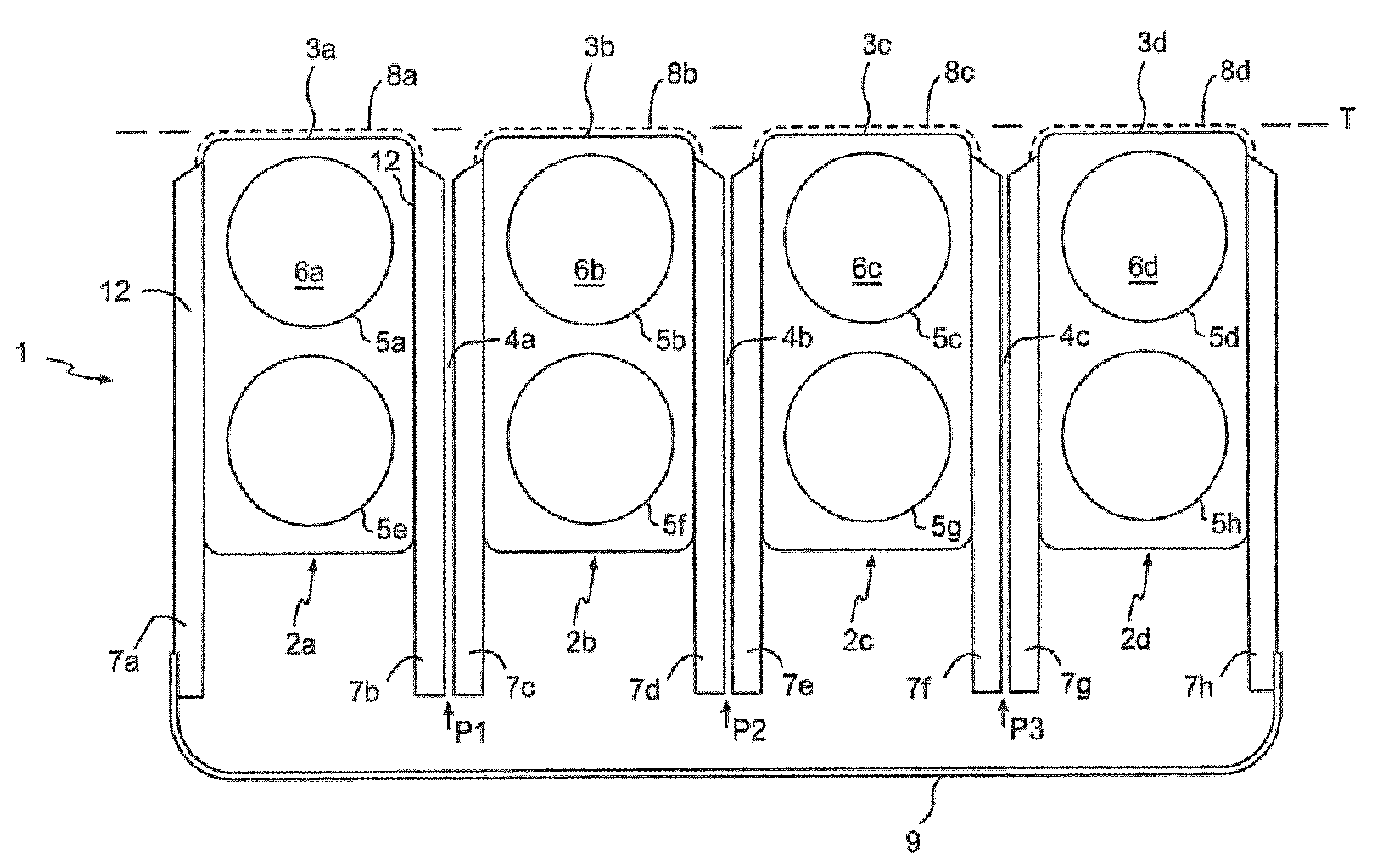
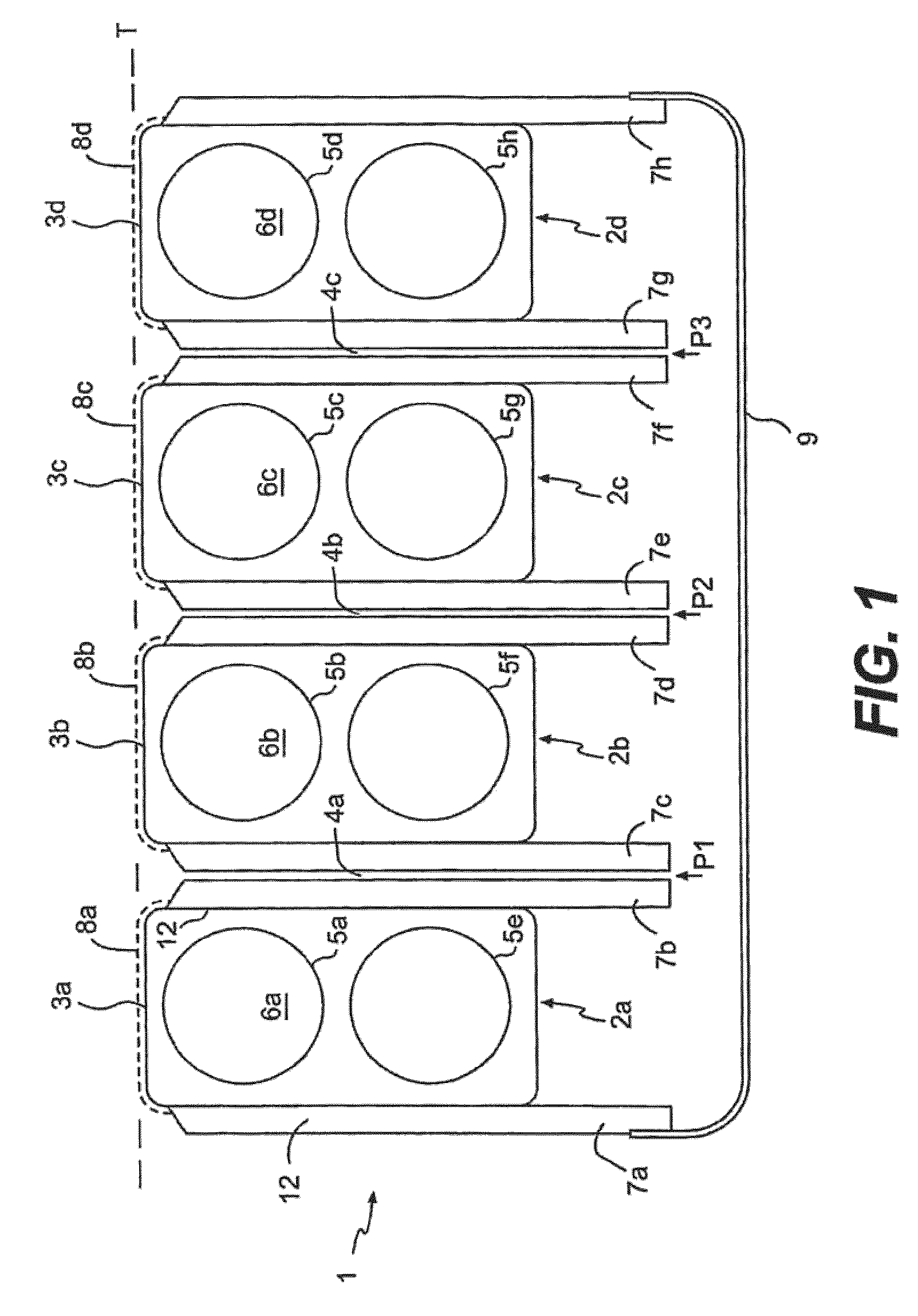
[0046]FIG. 1 shows a schematic cross sectional view of a first embodiment of a surface dielectric barrier discharge plasma unit 1 according to the invention. The unit 1 comprises an assembly of a multiple number of elongated shaped solid dielectric structure elements 2a, 2b, 2c, 2d. The elements 2a, 2b, 2c, 2d may be substantially arranged in parallel forming a solid dielectric structure such that an exterior treating surface 3a, 3b, 3c, 3d of each solid dielectric structure element 2a, 2b, 2c, 2d substantially extends in a common treating plane T. Alternatively, the elements 2a, 2b, 2c, 2d may be arranged so than respective exterior side surfaces of said elements are not exactly parallel to each other. This embodiment will be discussed in further detail with reference to FIG. 11. Further, inter spaces 4a, 4b, 4c between adjacent solid dielectric structure elements 2a, 2b, 2c, 2d define at least a part of gas flow paths P1, P2, P3 that extends along a surface of the solid dielectric...

Example

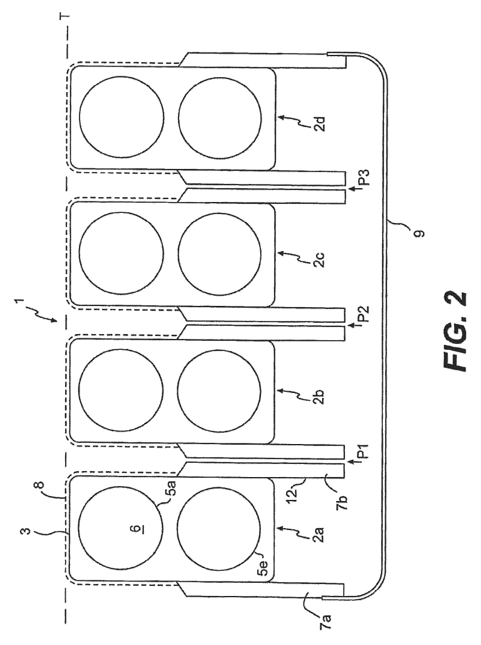
[0066]FIG. 2 shows a schematic cross sectional view of a second embodiment of a surface dielectric barrier discharge plasma unit 1 according to the invention. The exterior electrodes 7 partially cover exterior side surfaces 12 of the solid dielectric structure 2, thereby leaving upper sections of the exterior side surfaces uncovered. As a consequence, the region where the surface plasma is induced extends from the exterior treating surfaces 3 to the uncovered upper sections of the exterior side surfaces 12. The embodiment shown in FIG. 2 allows for the treatment of a surface by means of plasma activated gas, i.e. the flow of gas via the gas flow paths P1, P2, P3 between the exterior electrodes 7, in combination with a, possibly other, gas that is fed along the treatment plane T of the unit 1. This type of so-called plasma jet is effective in case of high gas velocity since there is a short time between production of reactive particles in the plasma and their transport to the surface...

Example

[0067]FIG. 3 shows a schematic cross sectional view of a third embodiment of a surface dielectric barrier discharge plasma unit 1 according to the invention. The unit 1 comprises an electrically conducting, earthed and perforated plate 10 extending at least partially along an exterior treating surface 3 of the solid dielectric structure 2. By providing the perforated plate 10 the distribution of the plasma activated gas is further improved. In this case it is preferred to apply a high gas speed, in order to limit loss of plasma reactivity by collisions between the reactive gas particles and between gas particles and the perforated plate before reaching the structure to be treated downstream. Further, a safer situation is obtained since the plate 10 is earthed. This option is advantageous when objects are treated in a space that is accessible for a person employing the plasma unit, e.g. for sterilization or disinfection purposes, such as floors, furniture, instruments or human skin.

[...


PUM


Abstract

The invention relates to a surface dielectric barrier discharge plasma unit. The unit comprises a solid dielectric structure provided with an interior space wherein an interior electrode is arranged. Further, the unit comprises a further electrode for generating in concert with the interior electrode a surface dielectric barrier discharge plasma. The unit is also provided with a gas flow path along a surface of the structure.

Description

FIELD OF THE INVENTION[0001]The invention relates to a surface dielectric barrier discharge plasma unit comprising a solid dielectric structure provided with an interior space wherein an interior electrode is arranged, further comprising a further electrode for generating in concert with the interior electrode a surface dielectric barrier discharge plasma, wherein the plasma unit is further provided with a gas flow path along a surface of the structure.BACKGROUND OF THE INVENTION[0002]Solid dielectric structures having electrode structures arranged on or embedded in the dielectric structures are known for performing plasma processes. A first electrode is positioned on a treating surface of the structure, while a second electrode is placed on the opposite side of the dielectric structure. In such a process, gas flows needed for the plasma process can be induced along a treating surface of the structure.[0003]Dedicated plasma units having an interior electrode are also known. The inte...

Claims


Application Information

Patent Timeline
IPC IPC(8): B01J19/08H05H1/24
CPCH05H1/2406H05H2001/245H05H1/245H05H1/2439H05H1/2441
Inventor CREYGHTON, YVES LODEWIJK MARIASIMOR, MARCELHUIJSER, TIMO
Owner NEDERLANDSE ORG VOOR TOEGEPAST-NATUURWETENSCHAPPELIJK ONDERZOEK (TNO)
Why Eureka
Try Eureka