Plasma processing apparatus, control method thereof and program for performing same

a plasma processing apparatus and control method technology, applied in the direction of coatings, chemical vapor deposition coatings, electric discharge tubes, etc., can solve the problems of inability to ensure the overall in-surface uniformity of plasma processing, the inability to perform and the inability to achieve plasma processing stably on the surface of semiconductor wafers. achieve the effect of maintaining the throughput of the plasma processing apparatus, reducing the number of cylindrical magn

Inactive Publication Date: 2009-09-08
TOKYO ELECTRON LTD
View PDF8 Cites 0 Cited by
  • Summary
  • Abstract
  • Description
  • Claims
  • Application Information

AI Technical Summary

Benefits of technology

[0012]In accordance with the aforementioned plasma processing apparatus, the method of controlling the plasma processing apparatus and the program for performing the method of controlling the plasma processing apparatus, it is determined whether the rotation driving mechanism is abnormal by detecting rotations of the bar-shaped magnets and clocking the rotations, and an comparing a time calculated from the clocked rotations to a specified time. Thus, it is possible to detect whether the rotations of the cylindrical magnets are stable or otherwise. Once unstable rotation has been detected, the plasma processing is stopped and maintenance is performed on the rotation driving mechanism to prevent the magnetic field in the processing chamber from becoming nonuniform. Further, given that detection of unstable rotation prompts the need for maintenance, it becomes possible to perform maintenance on the rotation driving mechanism at proper timings. Therefore, a plasma processing can be performed uniformly on the surface of the semiconductor wafer and, moreover, it becomes unnecessary to reduce the maintenance cycle of the rotation driving mechanism. Ultimately, the in-surface uniformity of plasma processing can be assured without compromising the steady and continuous operation of the plasma processing apparatus.
[0024]Preferably, the plasma processing apparatus includes a controller for controlling operations of components of the plasma processing apparatus based on operational states and state transitions, the operational states being defined as states of operations of the components in a plasma processing and the state transitions being defined as transitions between the operational states. That is, in the plasma processing apparatus, only defined operational states are performed and, likewise, a shift to a next operational state conforms to defined state transitions. Therefore, no component of the plasma processing apparatus performs any unnecessary operation, and this makes it possible to assure the proper operational states of the plasma processing. Further, operational states may be defined as desired, whereby desired operations can be controlled.

Problems solved by technology

However, for example, even if the cylindrical magnets can be rotated, if their rotational velocity is not stable due to breakdown, wear and tear etc. of the rotation driving mechanism, the magnetic field produced on the semiconductor wafer in the processing chamber will become nonuniform.
As a result, the plasma process cannot be performed stably on the surface of the semiconductor wafer.
Ultimately, the overall in-surface uniformity of the plasma processing cannot be guaranteed; for example, on the surface of a single semiconductor wafer, spots in OPEN condition (excessive etching) and SHORT condition (insufficient etching) will result during etch processing.
Generally speaking, the maintenance cycle of a driving mechanism needs to be shortened to avoid its breakdowns and wear and tear, but such measures will compromise the steady and continuous operation of the DRM type plasma processing apparatus.

Method used


Image

  • Plasma processing apparatus, control method thereof and program for performing same
  • Plasma processing apparatus, control method thereof and program for performing same
  • Plasma processing apparatus, control method thereof and program for performing same

Examples


Embodiment Construction

[0034]Preferred embodiments of the present invention will now be described with reference to the accompanying drawings.

[0035]First, a plasma processing apparatus in accordance with a first preferred embodiment of the present invention is explained.

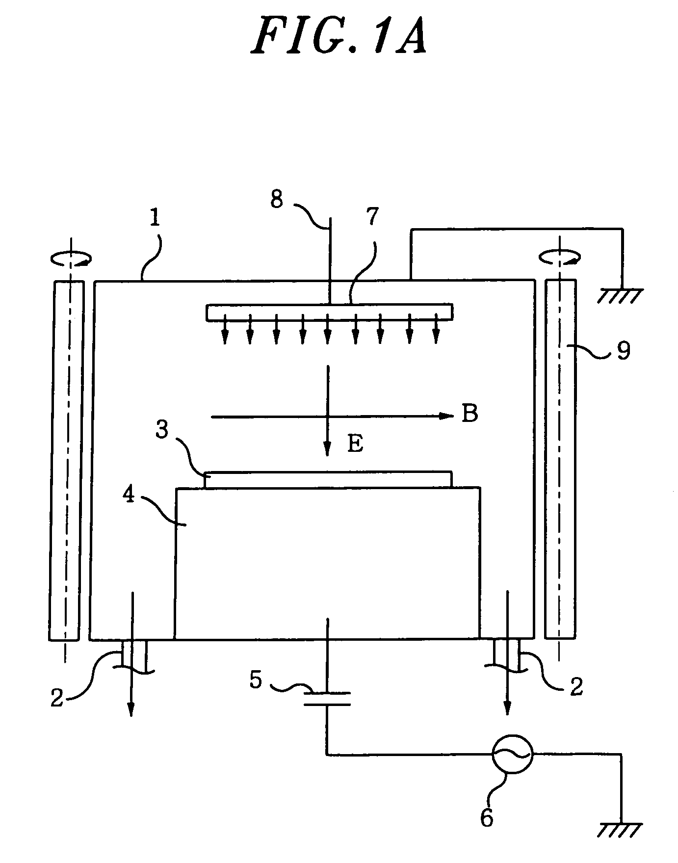
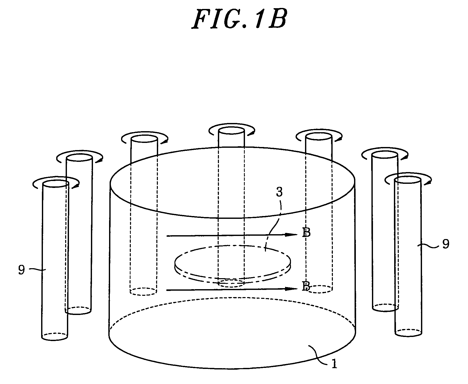
[0036]FIGS. 1A and 1B respectively show a cross sectional view and a perspective view of a schematic configuration of a DRM type plasma processing apparatus which is a plasma processing apparatus in accordance with the first preferred embodiment of the present invention.

[0037]The DRM type plasma processing apparatus shown in FIG. 1A includes a cylindrical processing chamber 1 made of a conductive material such as aluminum; gas exhaust pipes 2 connected to a lower portion of the processing chamber 1; a susceptor 4 serving as a lower electrode for mounting a semiconductor wafer 3 thereon, the susceptor 4 being disposed on a lower surface of processing chamber 1 and made of a conductive material such as aluminum; a high frequency power supply...


PUM

PropertyMeasurementUnit
pressureaaaaaaaaaa
pressureaaaaaaaaaa
frequencyaaaaaaaaaa

Abstract

A plasma processing apparatus includes a processing chamber for accommodating therein an object to be processed, a plurality of bar-shaped magnets rotatably installed standing around the processing chamber, a rotation driving mechanism for synchronously rotating the bar-shaped magnets, a rotation detection unit for detecting a rotation of a bar-shaped magnet and clocking times corresponding to the detected rotation, and an abnormal rotation determination unit for determining whether the rotation driving mechanism is abnormal by comparing an interval calculated from the clocked times to a time period.

Description

CROSS-REFERENCE TO RELATED APPLICATIONS[0001]This document claims priority to Japanese Patent Application Number 2004-202082, filed Jul. 8, 2004 and U.S. Provisional Application No. 60 / 598,426, filed Aug. 4, 2004, the entire content of which are hereby incorporated by reference.FIELD OF THE INVENTION[0002]The present invention relates to a plasma processing apparatus, a control method thereof and a program for performing the method; and, more particularly, a plasma processing apparatus including a processing chamber surrounded by a plurality of cylindrical magnets, a control method thereof and a program for performing the method.BACKGROUND OF THE INVENTION[0003]Conventionally, a DRM (Dipole Ring Magnet) type plasma processing apparatus has been utilized as an apparatus for performing a plasma process such as a film forming or etching process on a semiconductor wafer. The DRM type plasma processing apparatus includes a processing chamber for accommodating a semiconductor wafer therei...

Claims


Application Information

Patent Timeline
Patent Type & Authority Patents(United States)
IPC IPC(8): C23C16/00C23F1/00H01L21/306
CPCH01J37/3266H01L21/68792H01L21/67288H01L21/67069
Inventor YAMAZAKI, SATOSHITAKASE, TAIRA
Owner TOKYO ELECTRON LTD
Why Eureka
Try Eureka