Method of making a transparency

Inactive Publication Date: 2009-10-15
THE BOEING CO
View PDF6 Cites 12 Cited by
  • Summary
  • Abstract
  • Description
  • Claims
  • Application Information

AI Technical Summary

Benefits of technology

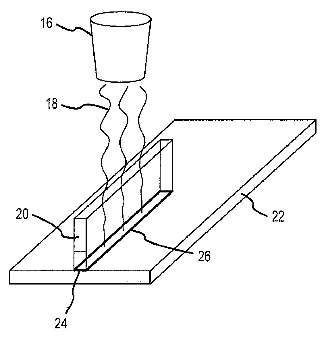
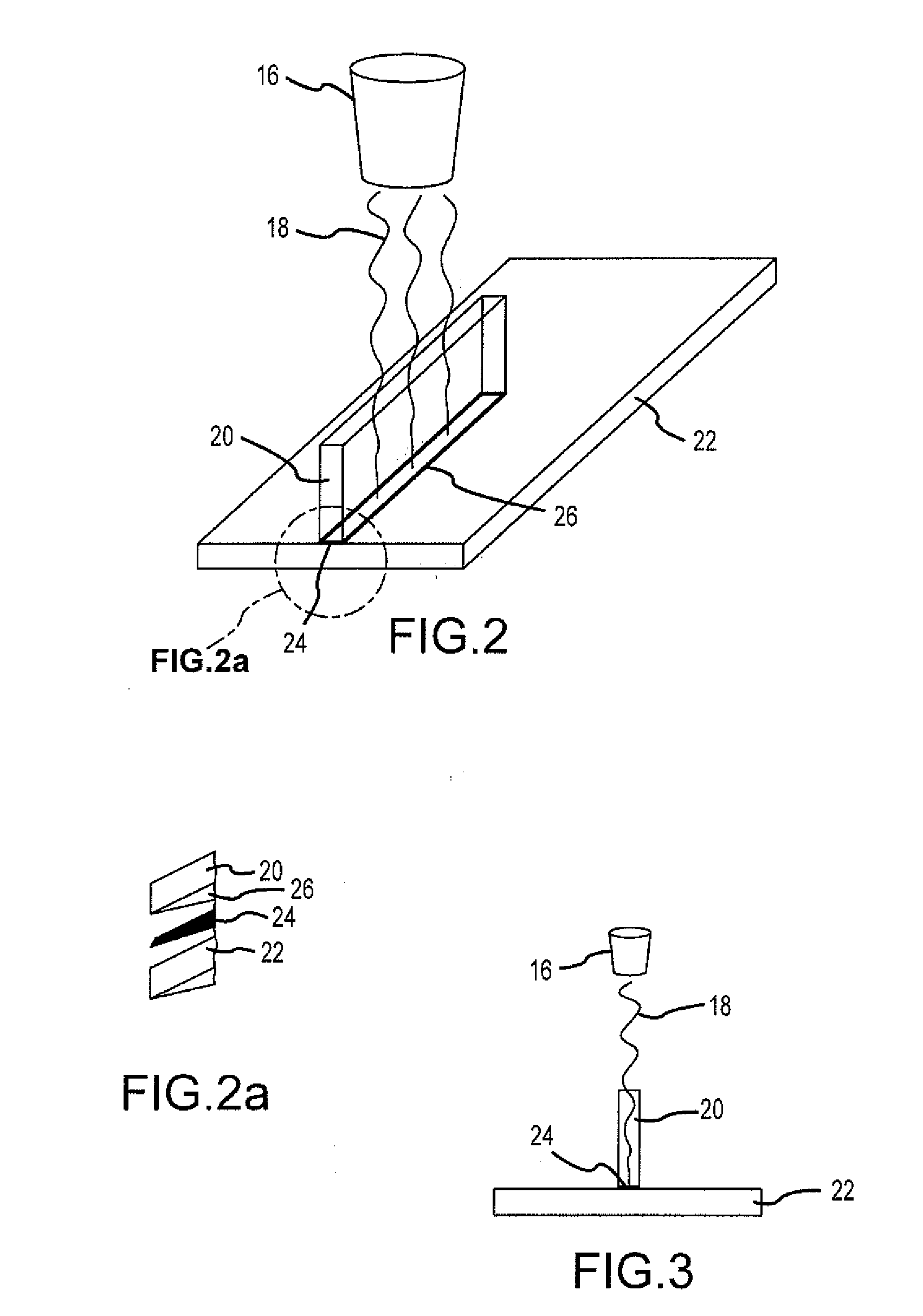
[0008]This need for a method of making a transparency by laser welding that does not have the problems associated with known methods, as well as a unique, nonobvious, and advantageous method, is satisfied. None of the known methods provides all of the numerous advantages discussed herein. Unlike known methods, embodiments of the method for making a transparency by laser welding, as well as the transparency made by the method, have one or more of the following advantages: the method avoids the use of a discrete, optically clear adhesive layer, such as polyurethane or silicone, that can cause the formation of air bubbles and result in optical distortion; the method provides a transparency with a welded joint that is optically transparent and has no optical distortion; the method provides a transparency that has a stronger joint than an adhesively bonded joint; the method provides control as to how much energy is applied to a joint as a function of time so that strength of the joint is improved; the method produces only one bond line rather than two bond lines as with adhesive bonding, and the method is highly repeatable and consistent; the method fuses two or more layers of transparent thermoplastics together using laser heat and results in a structural bond that is optically clear; the method has low heat input and thus low risk of thermal distortion or thermal damage, and the outer

Problems solved by technology

None of the known methods provides all of

Method used


Image

  • Method of making a transparency
  • Method of making a transparency
  • Method of making a transparency

Examples


Embodiment Construction

[0021]Embodiments of the invention will now be described more fully hereinafter with reference to the accompanying drawings, in which some, but not all embodiments of the invention are shown. Indeed, several different embodiments may be provided and should not be construed as limited to the embodiments set forth herein. Rather, these embodiments are provided so that this disclosure will be thorough and complete and will fully convey the scope of the invention to those skilled in the art. Like numbers refer to like elements throughout.

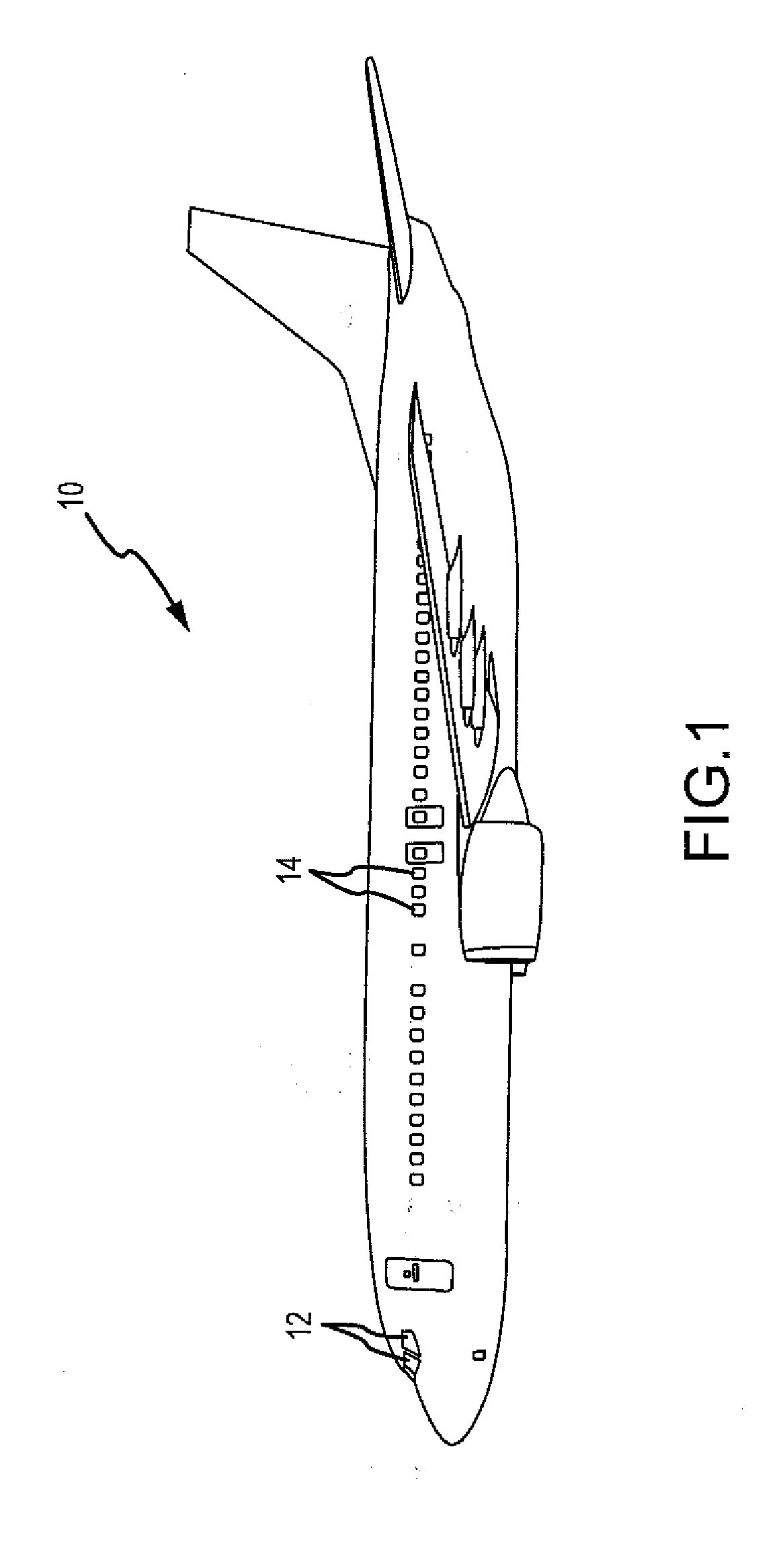
[0022]Referring now to the drawings, FIG. 1 is a side view of an airplane 10 showing various areas that can be welded using the method of the invention. Such areas may include windshields 12, passenger windows 14, and aircraft canopies (not shown) which are transparent enclosures over the cockpits of certain aircraft, such as light airplanes and fighter airplanes. The invention can be used for next generation aircraft transparencies, such as injection m...


PUM

PropertyMeasurementUnit
Widthaaaaaaaaaa
Widthaaaaaaaaaa
Transparencyaaaaaaaaaa

Abstract

A method of making a transparency is provided, the method comprising the steps of: layering at least two pieces of transparent thermoplastic, wherein a portion of at least one of the pieces of transparent thermoplastic is treated with a near infrared absorbing material; and, fusing the layered pieces of transparent thermoplastic together using a heat source to form an optically transparent and undistorted transparency. There is also provided a transparency comprising at least two layers of transparent thermoplastic, wherein the layers of transparent thermoplastic have been fused together using a heat source, such that the transparency is optically transparent and undistorted.

Description

BACKGROUND OF THE INVENTION[0001]1) Field of the Invention[0002]A method of making a transparency is provided. More particularly, a method of making a transparency by laser welding layers of optically transparent thermoplastics to achieve a transparency that is optically transparent and undistorted is provided.[0003]2) Description of Related Art[0004]Layers of thermoplastics are often joined together to assemble component parts such as windshields, windows, canopies, and assemblies thereof, for use in aircraft, vehicles, watercraft, and various other commercial products. A known method for joining such layers of thermoplastics together includes adhesively bonding the sheets together with an optically clear adhesive such as polyurethane, silicone, or polyvinyl butyral. However, a difficulty with this method is that air bubbles can become entrapped in the adhesive layer and can cause optical distortion of the layers. This can make clear viewing out of the windshields, windows, and can...

Claims


Application Information

Patent Timeline
IPC IPC(8): B32B27/16
CPCB29C65/1416B29C66/54B29C65/1483B29C65/1616B29C65/1674B29C65/1687B29C65/1696B29C65/5057B29C65/7841B29C66/301B29C66/43441B29C66/45B29C66/73366B29C66/939B29C2035/0822B29K2001/00B29K2001/12B29K2023/00B29K2023/06B29K2023/12B29K2025/00B29K2027/06B29K2027/16B29K2055/02B29K2067/00B29K2069/00B29K2071/00B29K2075/00B29K2077/00B29K2101/12B29K2995/0026B29L2009/00B32B37/06B32B37/26B32B38/1866B32B2307/412B32B2310/0843B32B2605/18B29C65/1603B29C65/1664B29C65/5021B29C65/1635B29C65/1683B29C65/169B29C65/4815B29C66/112B29C66/1122B29C66/114B29C66/9161B29C66/919B29C66/934B29C65/1435B29C66/71Y10T428/31507Y10T428/3154Y10T428/31551Y10T428/31786Y10T428/31855B29K2033/12B29K2027/18B29K2025/06
Inventor BOLSER, DAVID ROBERTBURNS, RICHARD W.BERKEL, THOMAS R.
Owner THE BOEING CO
Why Eureka
Try Eureka