Natural gas direct carbon fuel cell

a carbon fuel cell and natural gas technology, applied in the direction of fuel cells, cell components, fused electrolyte fuel cells, etc., can solve the problem of only 70% theoretical thermodynamic efficiency of hydrogen as fuel, and achieve the effect of improving hydrogen generation efficiency

Inactive Publication Date: 2009-10-15
HCE
View PDF6 Cites 33 Cited by
  • Summary
  • Abstract
  • Description
  • Claims
  • Application Information

AI Technical Summary

Benefits of technology

[0012]A natural gas fueled, direct carbon fuel cell produces electricity and hydrogen. It includes a cathode compartment comprising an oxygen-containing gas, a carbon dioxide feeding port and a molten electrolyte; an anode compartment comprising a port for feeding natural gas to the anode compartment, a hydrogen extraction port, a carbon dioxide extraction port, and a slurry comprising said molten electrolyte; and, an electron insulating, ion conducting, porous ceramic separator between the cathode compartment and the anode compartment. To improve hydrogen generation efficiency, the anode compartment may have a louvered baffle dividing the anode compartment into an ante-chamber adjacent to the port for feeding natural gas and a main chamber adjacent to the separator between the cathode compartment and the anode compartment. The louvered baffle preferably has an upper section with slats angled from bottom to top and a lower section with slats angled from top to bottom when viewed from a side wherein the port for feeding natural gas is on the left. Preferably included is a heat exchanger operably connected to transfer heat from hydrogen effluent out of the anode compartment to natural gas. It may also have a heat exchanger operably connected to transfer heat from nitrogen and carbon dioxide effluents out of the cathode compartment to the oxygen-containing gas.

Problems solved by technology

However, the theoretical thermodynamic efficiency of hydrogen as fuel is only 70%.

Method used


Image

  • Natural gas direct carbon fuel cell
  • Natural gas direct carbon fuel cell

Examples


Embodiment Construction

[0014]In the following description, reference is made to the accompanying drawings, which form a part hereof and which illustrate several embodiments of the present invention. The drawings and the preferred embodiments of the invention are presented with the understanding that the present invention is susceptible of embodiments in many different forms and, therefore, other embodiments may be utilized and structural and operational changes may be made without departing from the scope of the present invention.

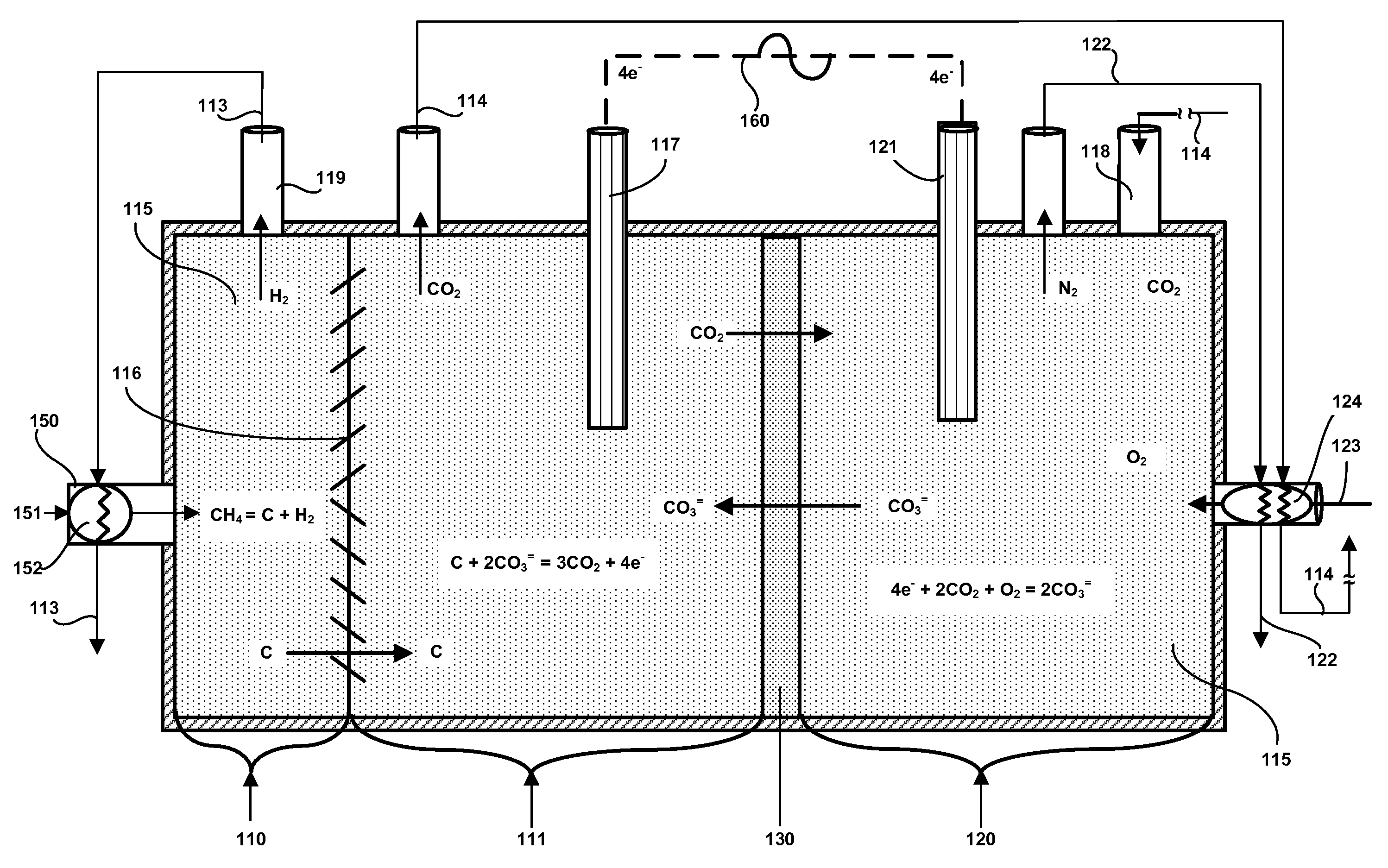
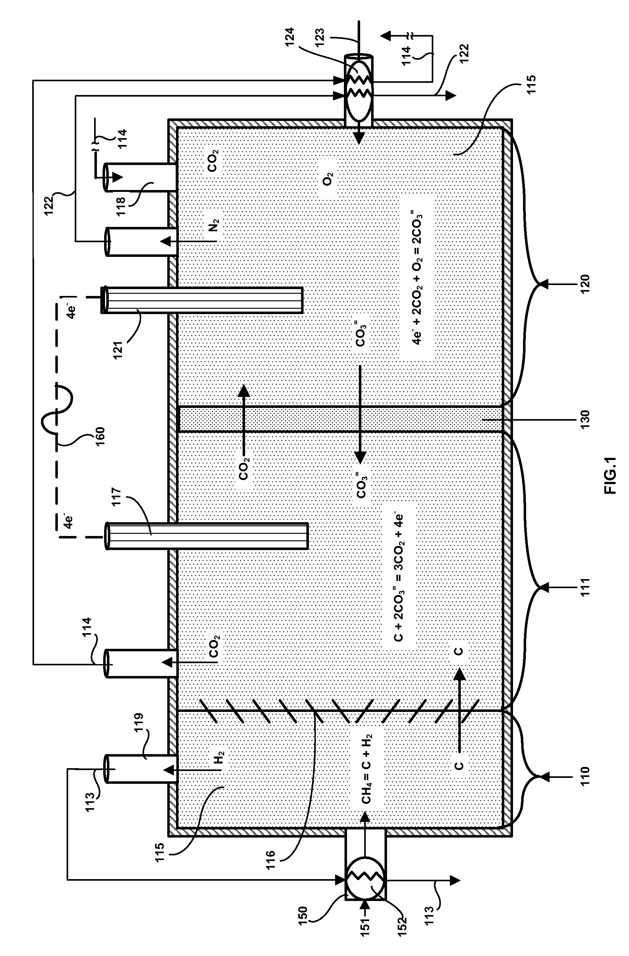
[0015]FIG. 1 is a diagram showing a sectional side view of a direct carbon fuel cell modified according to a preferred embodiment the invention. This invention uses natural gas (151), also known as methane. Natural gas and methane are used interchangeably herein. Natural gas (151) is a feed stock to produce coproducts hydrogen gas (113) and electricity (160) by combining molten-salt methane decomposition with the Direct Carbon Fuel Cell (DCFC) in one unit, known as Natural Gas Di...


PUM

PropertyMeasurementUnit
ion conductingaaaaaaaaaa
electrical currentaaaaaaaaaa
concentrationaaaaaaaaaa

Abstract

A natural gas fueled, direct carbon fuel cell produces electricity and hydrogen. It adds to an existing direct carbon fuel cell a carbon dioxide injection port to the cathode compartment; a natural gas feed port to the anode compartment, a hydrogen extraction port from the anode compartment, and a carbon dioxide extraction port from the anode compartment. To improve hydrogen generation efficiency, the anode compartment may have a louvered baffle dividing the anode compartment into an ante-chamber and a main chamber. The louvered baffle preferably has an upper section with slats angled from bottom to top and a lower section with slats angled from top to bottom. A heat exchanger is preferably included to pre-heat natural gas feed from hot hydrogen effluent. A second heat exchanger is preferably included to pre-heat oxygen-containing gas with hot nitrogen and carbon dioxide effluents.

Description

FIELD OF INVENTION[0001]In the field of chemistry, a fuel cell using a molten electrolyte is capable of producing hydrogen and an electrical current directly from natural gas supplied to the cell from an external source.BACKGROUND OF THE INVENTION[0002]Over the past several years, the Direct Carbon Fuel Cell has been under development for converting carbon directly to electricity. The Direct Carbon Fuel Cell is an electrochemical fuel cell that may be fueled with carbon. The cell comprises ash-free, turbostratic carbon particles derived from any source, including from pyrolysis of natural gas. However, none has proposed a means for directly decomposing natural gas within a Direct Carbon Fuel Cell while extracting hydrogen gas from the cell and leaving the carbon particles within the cell.[0003]No Direct Carbon Fuel Cell to date has been directly fueled with natural gas (methane) or gaseous and liquid carbonaceous fuels. The invention described herein uses methane or natural gas as f...

Claims


Application Information

Patent Timeline
Patent Type & Authority Applications(United States)
IPC IPC(8): H01M2/14H01M8/00
CPCH01M8/0236Y02E60/526H01M2008/147H01M8/14Y02E60/50
Inventor STEINBERG, MEYER
Owner HCE
Why Eureka
Try Eureka