Method for making thermal electron emitter

a technology of thermal electron emitter and emitter, which is applied in the manufacture of discharge tube main electrodes, electrode systems, electric discharge tube/lamps, etc., can solve the problems of less stable thermal electron emitter devices and low lifespan of electron emitter devices

Active Publication Date: 2009-10-15
TSINGHUA UNIV +1
View PDF13 Cites 10 Cited by
  • Summary
  • Abstract
  • Description
  • Claims
  • Application Information

AI Technical Summary

Problems solved by technology

Further, thermal electron emission devices are less stable because alkaline earth metal oxide is easy to vaporize at high temperatures.
Consequently, the lifespan of the electron emission device tends to be low.

Method used


Image

  • Method for making thermal electron emitter
  • Method for making thermal electron emitter
  • Method for making thermal electron emitter

Examples


Embodiment Construction

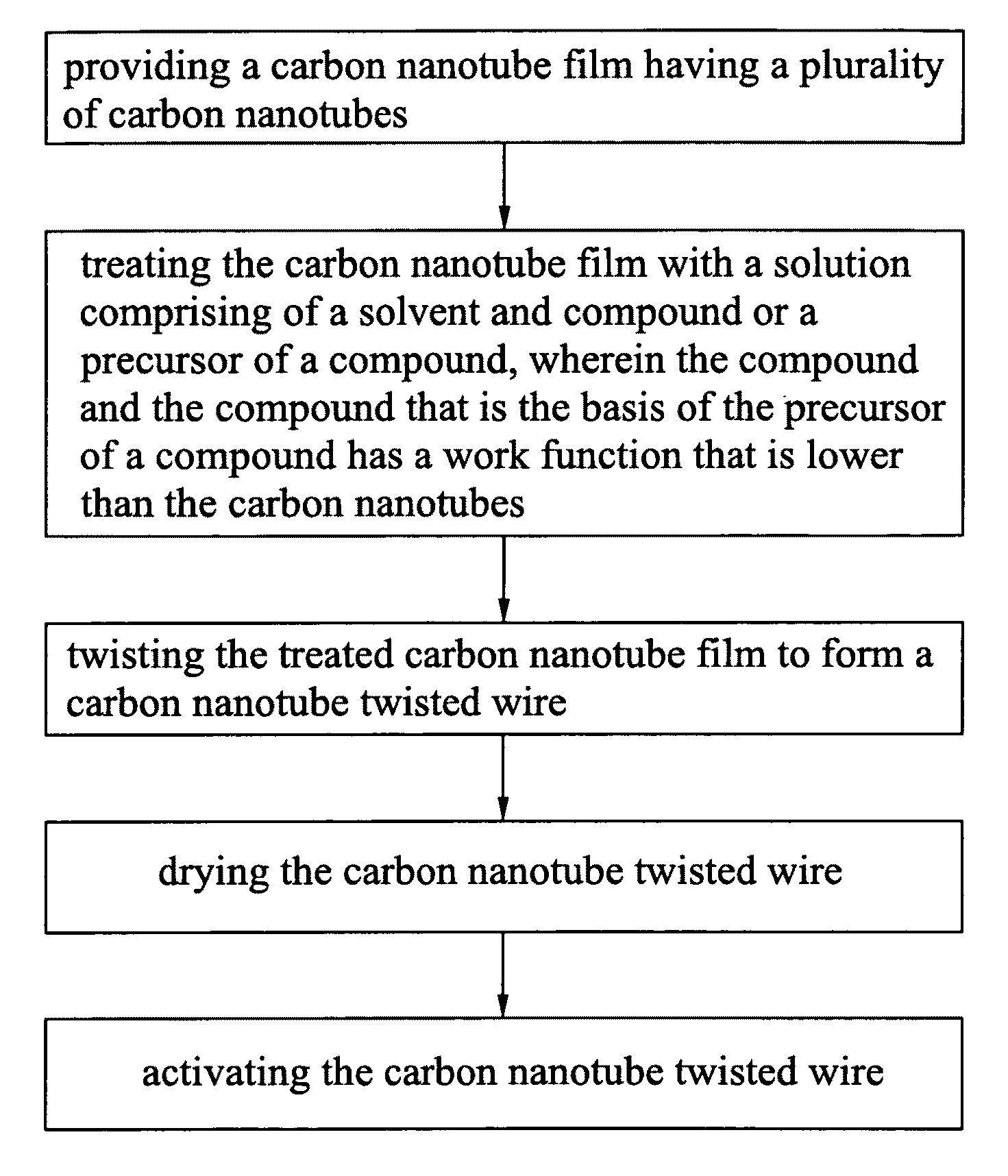
[0012]References will now be made to the drawings to describe, in detail, various embodiments of the present method for making the thermal electron emitter.

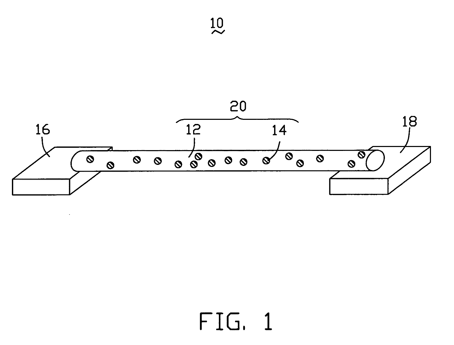
[0013]Referring to FIG. 1, a thermal electron emission device 10 includes a thermal electron emitter 20, a first electrode 16, and a second electrode 18. The thermal electron emitter 20 includes a carbon nanotube twisted wire 12 and a number of electron emission particles 14. The twisted wire 12 is configured to serve as a matrix. The electron emission particles 14 are uniformly dispersed either inside or on surface of the twisted wire 12. Two opposite ends of the twisted wire 12 are electrically connected to the first electrode 16 and the second electrode 18, respectively. In the present embodiment, the twisted wire 12 is contacted to the first electrode 16 and the second electrode 18 with a conductive paste / adhesive, such as a silver paste.

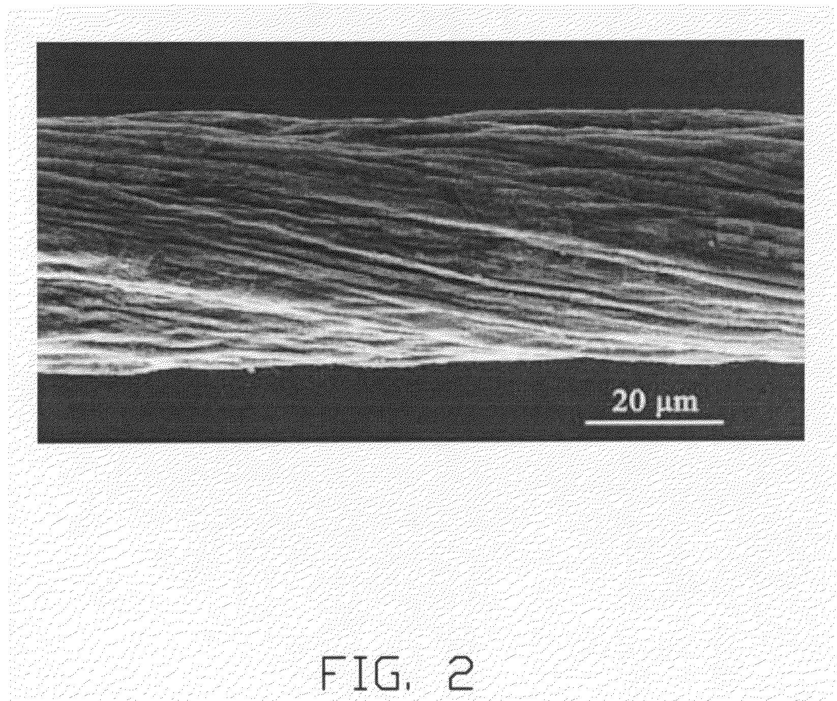
[0014]Referring to FIG. 2, the twisted wire 12 includes a plurality of successively orien...


PUM

PropertyMeasurementUnit
timeaaaaaaaaaa
temperatureaaaaaaaaaa

Abstract

A method for making the thermal electron emitter includes following steps. Providing a carbon nanotube film including a plurality of carbon nanotubes. Treating the carbon nanotube film with a solution comprising of a solvent and compound or a precursor of a compound, wherein the compound and the compound that is the basis of the precursor of a compound has a work function that is lower than the carbon nanotubes. Twisting the treated carbon nanotube film to form a carbon nanotube twisted wire. Drying the carbon nanotube twisted wire. Activating the carbon nanotube twisted wire.

Description

RELATED APPLICATIONS[0001]This application is related to commonly-assigned, co-pending application: U.S. patent application Ser. No. 12 / 006,305, entitled “METHOD FOR MANUFACTURING FIELD EMISSION ELECTRON SOURCE HAVING CARBON NANOTUBES”, filed ______ (Atty. Docket No. US16663); U.S. patent application Ser. No. 12 / 080,604, entitled “THERMAL ELECTRON EMISSION SOURCE HAVING CARBON NANOTUBES AND METHOD FOR MAKING THE SAME”, filed ______ (Atty. Docket No. US16664); and U.S. patent application Ser. No. ______, entitled “THERMAL ELECTRON THERMAL ELECTRON EMITTER AND THERMAL ELECTRON EMISSION DEVICE USING THE SAME”, filed ______ (Atty. Docket No. US19047). The disclosure of the above-identified application is incorporated herein by reference.BACKGROUND[0002]1. Field of the Invention[0003]The present invention relates to a method for making a thermal electron emitter based on carbon nanotubes.[0004]2. Discussion of Related Art[0005]Thermal electron emission devices are widely applied in gas l...

Claims


Application Information

Patent Timeline
Patent Type & Authority Applications(United States)
IPC IPC(8): H01L21/62
CPCH01J1/15H01J1/14
Inventor XIAO, LINLIU, LIANGLIU, CHANG-HONGFAN, SHOU-SHAN
Owner TSINGHUA UNIV
Why Eureka
Try Eureka