Supercharged internal combustion engine system

a technology of internal combustion engine and supercharger, which is applied in the direction of electrical control, process and machine control, instruments, etc., can solve the problems of reducing the power and torque of downsized engines with reduced swept volume, limiting the density of turbocharged ice, and limiting the response time of turbocharged ice, so as to increase the density, increase the weight of ice charge, and increase the effect of ice output power

Inactive Publication Date: 2009-10-15
AGWEST
View PDF3 Cites 23 Cited by
  • Summary
  • Abstract
  • Description
  • Claims
  • Application Information

AI Technical Summary

Benefits of technology

[0008]The present invention provides a supercharged ICE system wherein the supercharger assembly comprises a turboexpander expanding high-pressure air that supplies cold, dense air to ICE combustion chamber. Intake of dense air increases the weight of ICE charge and thus enables increase of ICE output power. The supercharger assembly may also include an ejector pump operated by cold air from the turboexpander. The nozzle pumps intake air thereby increasing its density both by compression and by cooling. The supercharger assembly may also include a turbocompressor for feeding compressed air into the ICE intake. The turbocompressor is operated by the energy extracted by the turboexpander from expanding high-pressure air. The supercharged ICE system may further include means for regulating the flow and / or pressure of high-pressure air fed to the turboexpander and thereby regulating the supercharging action. In addition, the supercharged ICE system may include means for sensing ICE power demand and appropriately controlling the operation of the turboexpander and of the turbocompressor pump (if used) to supercharge the ICE in response to demand.

Problems solved by technology

However, downsized engines having reduced swept volume typically exhibit insufficient power and torque when operating with normal aspiration.
The compression of intake air increases its temperature and thus undesirably limits its density.
A turbocharged ICE is susceptible to a slow response time known as the “turbo lag” which is caused by the low pressure and low quantity of exhaust gases that are available to operate the turbine at low engine speeds.
This translates to insufficient quantity of intake air delivered to the engine and results in insufficient torque at low engine speeds.
However, this approach provides only a partial solution, adds complexity and cost, and reduces reliability.
A drawback of this approach is that during acceleration of the e-turbo to operational speed the electric motor has to overcome the compound inertia of both the turbo-compressor and the exhaust turbine while additionally being exposed to very high temperatures.
However, both e-turbo approaches face the challenge of attaining the extremely fast startup and acceleration to reach operating speeds of 50,000 to 70,000 revolutions per minute (rpm) in less than one second.
In particular, according to an article authored by Thomas Kattwinkel et al. entitled “Mechatronic Solution for Electronic Turbocharger” SAE paper number 2003-01-0712 published by the Society of Automotive Engineers, Inc., Warrendale, Pa., the e-turbo electric demand may not be satisfactorily met with the standard 12 volt automotive battery system.
In summary, prior art does not teach a supercharged ICE system that is effective during the conditions of high torque and low engine speed, has a fast response, is simple, economical, and can be easily retrofitted onto existing ICE, does not require exotic electric motors and power supply, avoids exposing electrical components to high temperatures, and reduces susceptibility to charge pre-ignition.
Furthermore, the prior art does not teach an ICE where intake air is mixed with cold air from a turboexpander.
Moreover, prior art does not teach an ICE supercharged by an a turbocompressor operated by a turboexpander expanding high-pressure air, wherein compressed intake air produced by the turbocompressor is cooled by the cold air produced by the turboexpander.

Method used


Image

  • Supercharged internal combustion engine system
  • Supercharged internal combustion engine system
  • Supercharged internal combustion engine system

Examples


Embodiment Construction

[0027]Selected embodiments of the present invention will now be explained with reference to drawings. In the drawings, identical components are provided with identical reference symbols. It will be apparent to those skilled in the art from this disclosure that the following descriptions of the embodiments of the present invention are merely exemplary in nature and are in no way intended to limit the invention, its application, or uses.

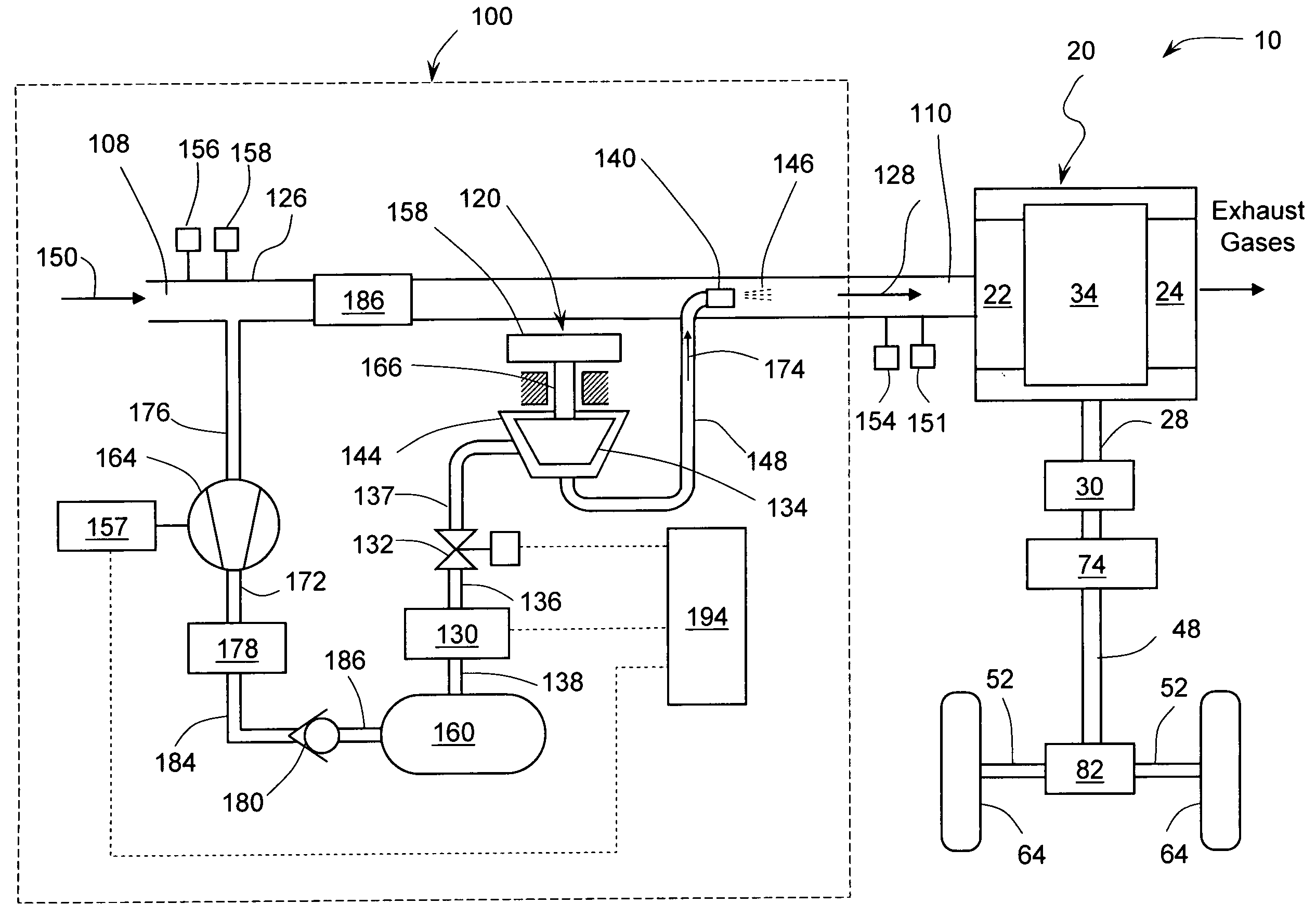
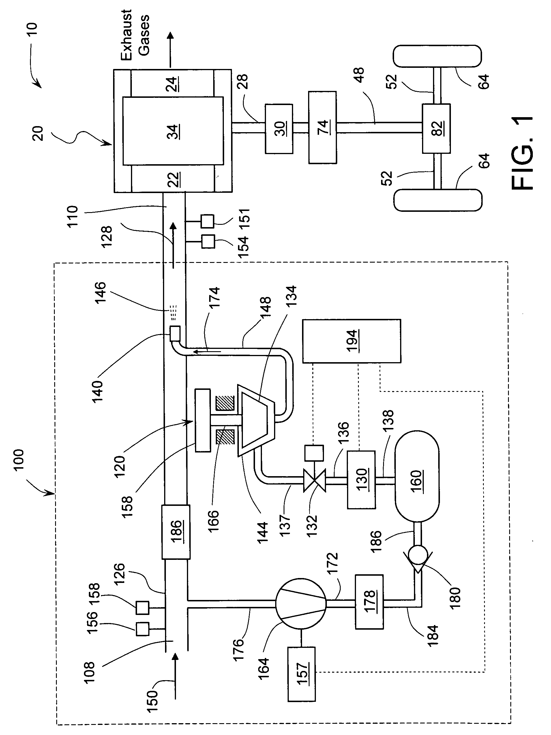
[0028]Referring to FIG. 1, there is shown a supercharged internal combustion engine (ICE) system 10 in accordance with a first embodiment of the subject invention. The ICE system 10 comprises an ICE 20 and a supercharger assembly 100. The ICE 20 has at least one combustion chamber 34 fluidly coupled to an intake passage 22 and to an exhaust passage 24. The type of ICE 20 can be either a compression ignition (diesel), a fuel injected spark ignition, carbureted spark ignition, or homogeneous charge compression ignition (HCCI) also known as controlled aut...


PUM


Abstract

A supercharged internal combustion engine system wherein during periods of high power demand the weight of combustion chamber charge is increased by cooling a portion of intake air in a turboexpander using high-pressure air from a storage tank. In addition to increasing engine output power, cold air intake also reduces engine pre-ignition (knocking) thereby reducing emissions. Mechanical energy produced during expansion of high-pressure air may be used to operate a turbocompressor, which compresses intake air and further increases charge weight. Effective supercharging is achieved even at low engine speeds. One of the objects of the invention is to obtain more power from small displacement ICE and thus providing automotive vehicles with sufficient acceleration in addition to good fuel economy. Another object of the invention is to enhance turbocharged engines and reduce their response lag. Air storage tank may be recharged using energy recovered during vehicle deceleration.

Description

CROSS-REFERENCE TO RELATED APPLICATIONS[0001]This application claims priority from U.S. provisional patent application U.S. Ser. No. 61 / 124,090, filed on Apr. 14, 2008.FIELD OF THE INVENTION[0002]This invention relates generally to supercharged internal combustion engines and, more particularly, to superchargers capable of fast response to engine demand and delivering boost independent of engine speed.BACKGROUND OF THE INVENTION[0003]Supercharging of Internal Combustion Engines: One of the long-term goals of the automotive manufacturers is to reduce fuel consumption and emissions of modern automotive vehicles powered by internal combustion engines (ICE) while increasing engine efficiency. One approach to reaching this goal is reducing the ICE displacement. However, downsized engines having reduced swept volume typically exhibit insufficient power and torque when operating with normal aspiration. Performance of downsized engines may be recovered by supercharging. It is well known in ...

Claims


Application Information

Patent Timeline
Patent Type & Authority Applications(United States)
IPC IPC(8): F02D43/00F02B33/00
CPCF02B33/40F02B39/08Y02T10/144F02D23/005F02D41/0007F02D23/00Y02T10/12
Inventor VETROVEC, JAN
Owner AGWEST
Why Eureka
Try Eureka