System for controlling the position and orientation of an object in dependence on received forces and torques from a user

a technology of receiving force and torque, applied in the direction of programme control, force/torque/work measurement apparatus, instruments, etc., can solve the problems of failure to achieve the effect of robotics investment, difficulty in small and medium-sized enterprises to invest in robotics, and difficulty in programming using joystick and advanced computer programs

Inactive Publication Date: 2009-10-15
ABB (SCHWEIZ) AG
View PDF7 Cites 178 Cited by
  • Summary
  • Abstract
  • Description
  • Claims
  • Application Information

AI Technical Summary

Benefits of technology

[0013]The object of the present invention is to provide an improved system for controlling the position and orientation of an object in dependence on forces and torques from a user, which alleviates the drawbacks of the prior art systems mentioned above.

Problems solved by technology

Because of the complexity of robot programming, it is difficult for small and medium sized enterprises to invest in robotics.
However, looking at the tools carried by the robot and used for performing the same actions, there is no aid for any interaction with the craftsman and therefore very difficult programming must be performed using joystick and advanced computer programs.
There have been developments of programming systems where the tools have been mounted on measurement arms or where the tools have been equipped with light emitting diodes or reflectors to be measured by optical measurement systems, but these solutions have not been successful because of high cost of the measurement system and lacking robustness of the measurement system, and the impossibility to use heavy tools or work objects on the measurement arm.
However, a force-torque sensor, which is able to support the force / torque levels from the tool or work object, will not be sensitive enough, and has not the bandwidth needed for accurate and efficient manipulation.
Consequently, the sensor size is large and the sensitivity is small.
Problems with using this type of force-torque sensor are that they are expensive to produce and too large for many applications.
They are expensive since the steel structure is complicated to be machined.
The smaller the sensor is, the more difficult is the gluing of the sensors.
The manufacturing methods used, such as high precision machining and high precision assembly, are not possible to make cheap, not even at large production volumes.
However, such a handle is difficult to use since it may collide with other objects in the workspace and can be difficult to reach when programming more complicated trajectories.
A problem, which occurs when the proposed sensor is to be used in the above mentioned lead-through programming application is that the silicon is very stiff and fragile and thus can be easily broken into pieces for the force ranges needed in this application.

Method used


Image

  • System for controlling the position and orientation of an object in dependence on received forces and torques from a user
  • System for controlling the position and orientation of an object in dependence on received forces and torques from a user
  • System for controlling the position and orientation of an object in dependence on received forces and torques from a user

Examples


Embodiment Construction

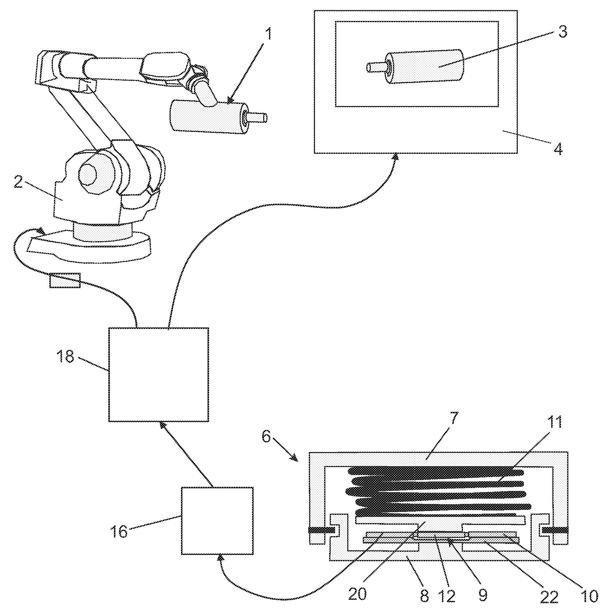
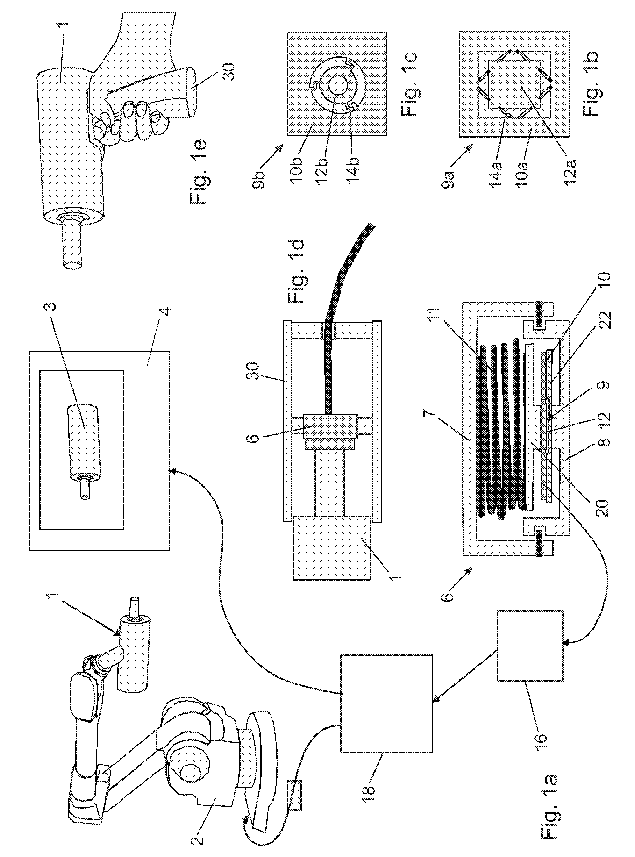
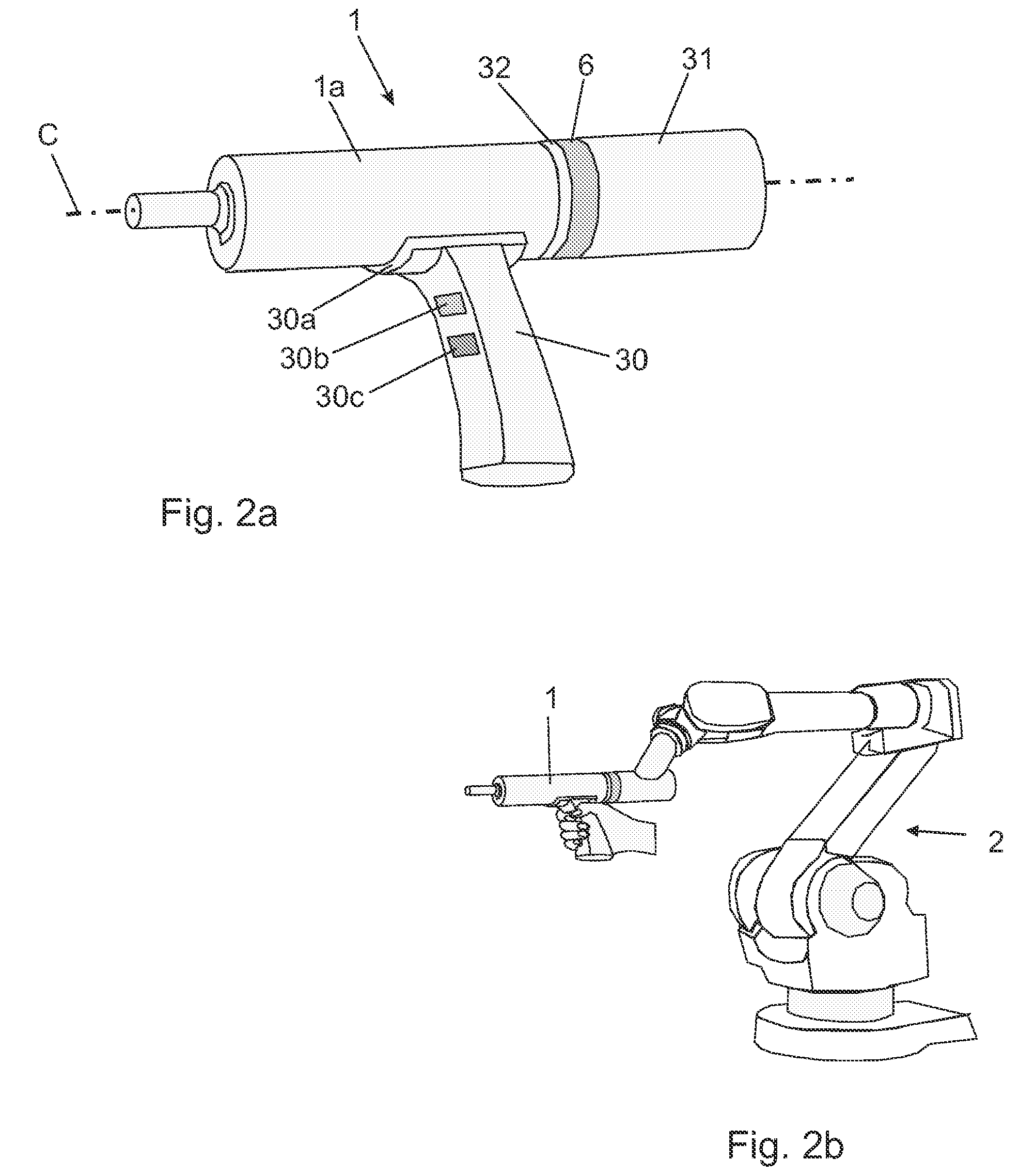
[0096]FIG. 1a shows a system used by a human operator to control the position and orientation of an object, which can be a real object 1 manipulated by a robot 2, or a virtual object 3 displayed on a computer screen 4. The system comprises a measuring assembly 6 for measuring forces and torques, which includes a first part 7, in this example a sensor housing, adapted to receive forces and torques from a human operator, and a second part 8, in this example a sensor flange, wherein the first and second parts are arranged movable relative to each other. The measuring assembly 6 further comprises a sensor unit adapted to measure forces and torques caused by changes in position and orientation of the first part 7 in relation to the second part 8. The sensor comprises a semiconductor sensor chip 9 and measuring electronics 16.

[0097]FIG. 1b shows an example of a semiconductor sensor chip 9a comprising an outer rectangular plate 10a and an inner rectangular plate 12a, which are mechanically...


PUM

PropertyMeasurementUnit
diameteraaaaaaaaaa
thicknessaaaaaaaaaa
angleaaaaaaaaaa

Abstract

A system for controlling position and orientation of an object. A first part is adapted to receive forces and torques from a user. A sensor is adapted to measure forces and torques caused by changes in position and orientation of the first part relative to a second part. A data processing unit is arranged to receive measured data from the sensor and based thereon to control the position and orientation of the object. The sensor includes a semiconductor chip with integrated sensor elements. The measuring assembly includes a spring arrangement mounted between the first and second parts and mechanically connected to the sensor for converting forces and torques from the user to changes in position and orientation of the first part relative to the second part. The sensor is adapted to measure forces and torques from the spring arrangement caused by the changes in position and orientation of the first part.

Description

FIELD OF THE INVENTION[0001]The present invention relates to a system for controlling the position and orientation of an object in dependence on received forces and torques from a user. The system is used by a human operator to control the position and orientation of an object, which can be a real object, for instance manipulated by an industrial robot, or a virtual object on a computer screen. The system is, for example, useful in a joystick controlling an object on a computer screen, or for controlling a tool or a work object manipulated by an industrial robot in connection with lead-through programming of the robot. It can also be used in other applications where manipulation in several degrees of freedom is necessary, as for example for telemetry operated robots, which are needed in hazardous environment, in sub sea vehicles, on excavation machines, in surgery equipment, in space stations and vehicles etc. Even if the invention has its main applications for human machine interac...

Claims


Application Information

Patent Timeline
Patent Type & Authority Applications(United States)
IPC IPC(8): G01L5/00G06F15/00
CPCB25J9/1633B25J13/085G01L5/162G05B19/423G05B2219/41114G05B2219/36433G05B2219/39439G05B2219/39529G05B2219/40599G05B2219/36425
Inventor BROGARDH, TORGNY
Owner ABB (SCHWEIZ) AG
Why Eureka
Try Eureka