
Method and device for fast correlation calculation

a fast correlation and calculation method technology, applied in the field of fast correlation calculation, can solve the problems of insufficient reduction of the total duration of the calculation of the correlation obtained by the first solution, and achieve the effects of reducing the duration of an elementary correlation calculation, reducing the number of arithmetic operations, and increasing the duration of the aggregation

Active Publication Date: 2009-10-15
THALES SA
View PDF6 Cites 52 Cited by
  • Summary
  • Abstract
  • Description
  • Claims
  • Application Information

AI Technical Summary

Benefits of technology

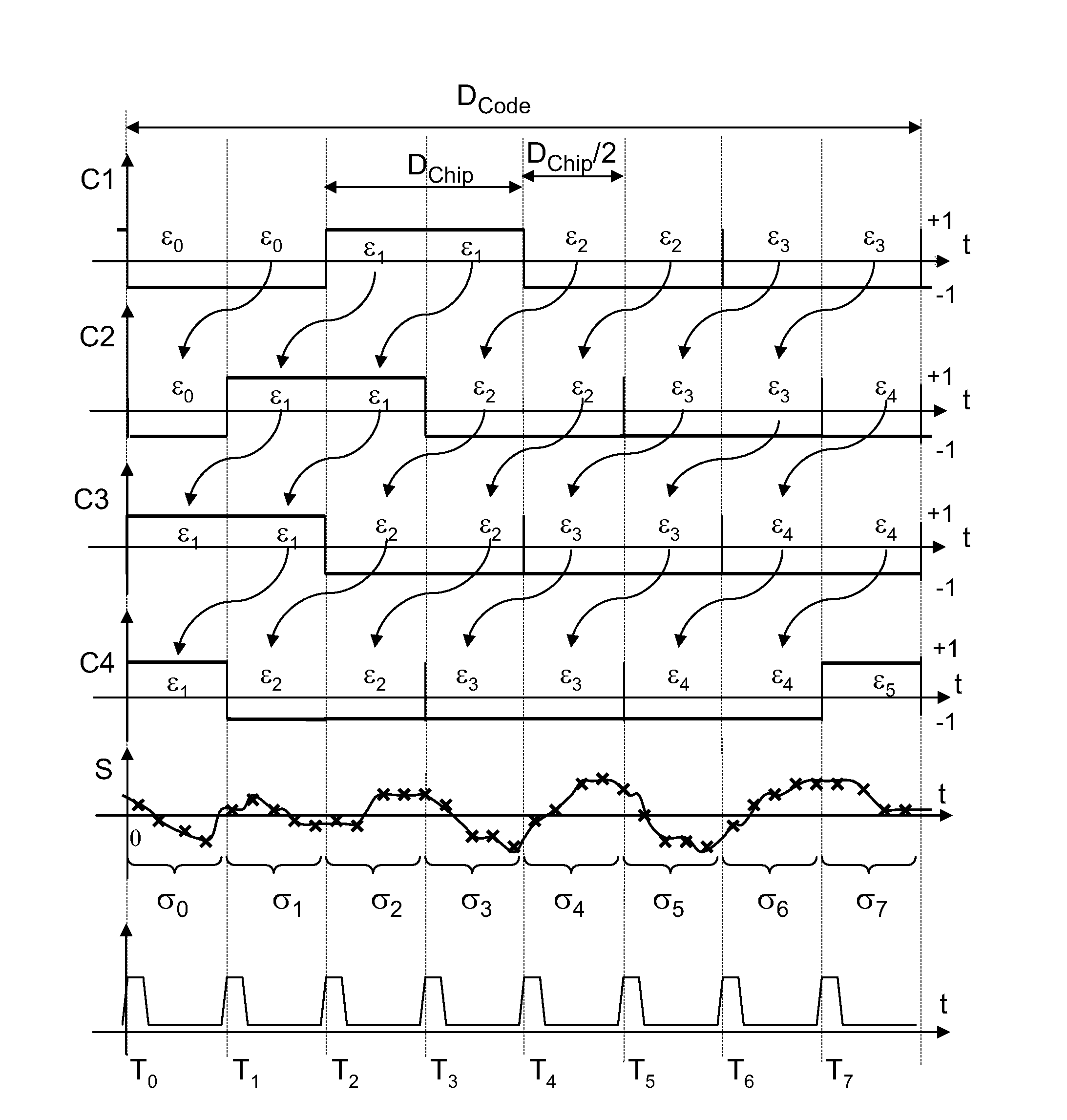
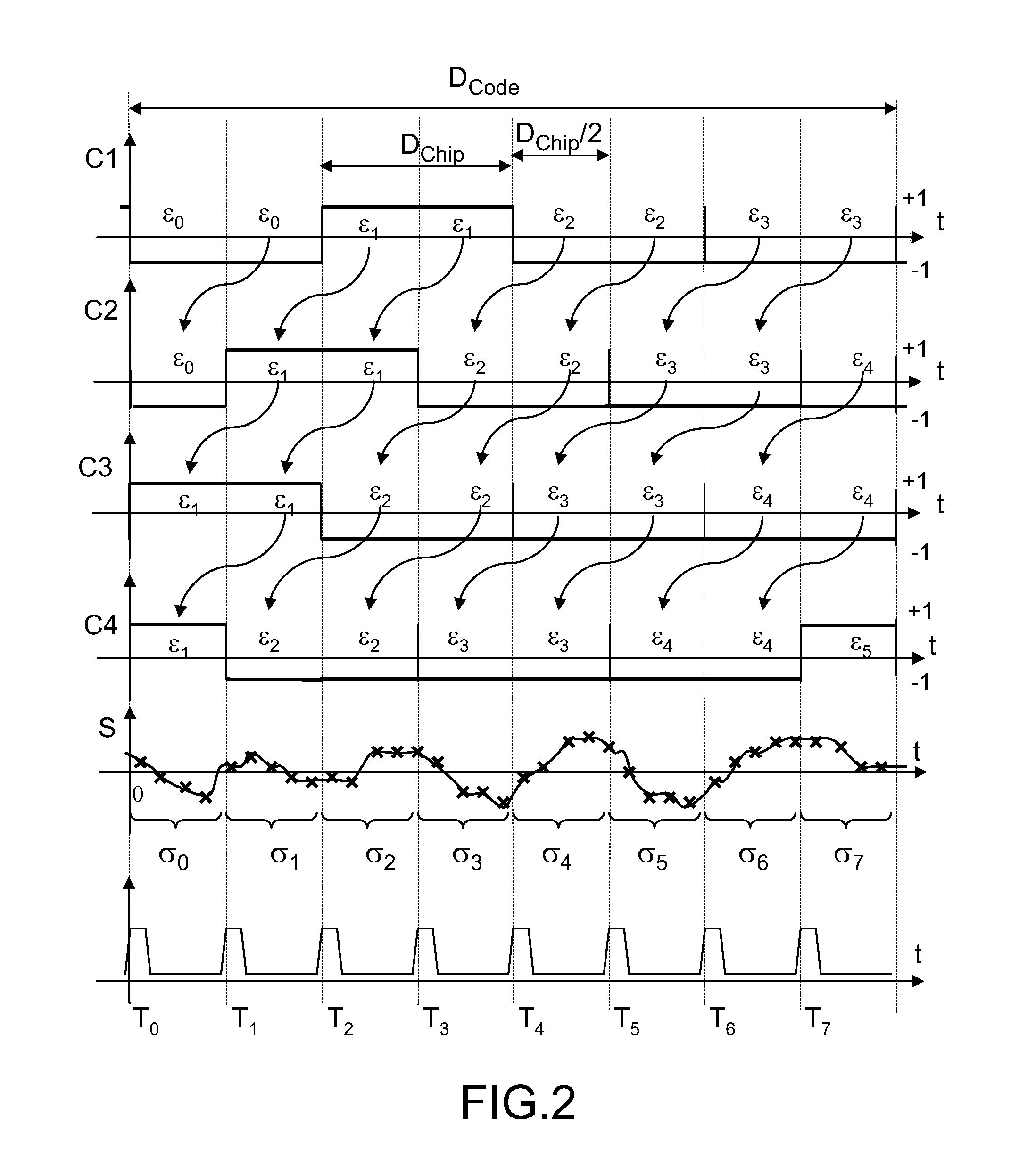
[0015]A first advantage of the invention is that it contributes to reducing the duration of an elementary correlation calculation. Specifically, aggregation of samples of the second sequence makes it possible, as will be shown further on, to reduce the number of arithmetic operations to be carried out to obtain an elementary correlation calculation result, notably products between samples of code and of signal. Aggregation is equivalent to common factoring which is made possible by the stability of the value of the code over the duration of the aggregation. This advantage of the invention is all the more significant the higher the duration of the aggregation with respect to the duration of a sample of signal at Fe of the second sequence.

Problems solved by technology

In a certain number of situations, the reduction obtained in the total duration of the calculation of the correlations by the first solution presented is not sufficient, this being the case for example when the period T of the code is long or when the number of elementary correlations to be performed is multiplied because of a significant number of assumptions to be made about the frequency of the signal to be considered in order to compensate for the Doppler effect.

Method used


Image

  • Method and device for fast correlation calculation
  • Method and device for fast correlation calculation
  • Method and device for fast correlation calculation

Examples


Embodiment Construction

[0029]From one figure to another, the same elements are labeled by the same references.

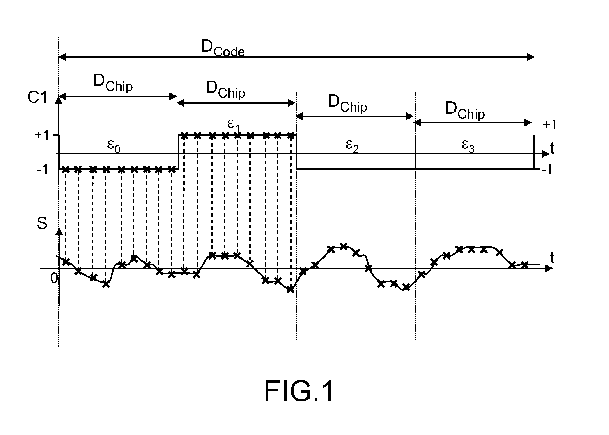
[0030]FIG. 1 represents, along one and the same time axis, a temporal evolution C1(t) of a pseudo-random code generated by a receiver of a satellite positioning system, and a temporal evolution S(t) of a radionavigation signal received by the receiver.

[0031]The pseudo-random code is a signed binary code, equaling +1 or −1, which is generated locally by the receiver of a satellite positioning system. The locally generated code has a duration DCode, it comprises elementary time divisions, called code chips, of mean duration Dchip. To simplify the representation of FIG. 1, a code comprising four chips has been chosen, but the code could comprise a much bigger number of chips, for example 1024, or more. Over the duration of a chip, the code retains a constant value: the successive values taken by the code are named εi where i is an index identifying a chip of the code generated by the receiver.

[0032]O...


PUM


Abstract

The field of the invention is that of the reception of a radionavigation signal originating from a satellite positioning system such as the GPS system. The present invention concerns a method for calculating correlations between a first sequence and a second sequence, said first sequence and said second sequence having a duration DCode, the first sequence being extracted from a digital signal comprising a code, said code comprising elementary time divisions, called chips, of mean duration Dchip, said chips being synchronized with pulses delivered by an NCO oscillator at the mean frequency 2 / Dchip, the second sequence resulting from a sampling at a frequency Fe of an analog signal, the frequency Fe being greater than 2 / Dchip. According to the invention, the method comprises a step of aggregating samples of the second sequence, over consecutive integration intervals of duration equal on average to Dchip / 2, starting at each pulse of the NCO oscillator, so as to determine results of elementary aggregates.

Description

CROSS-REFERENCE TO RELATED APPLICATIONS[0001]The present Application is based on International Application No. PCT / EP2007 / 052037, filed on Mar. 5, 2007, which in turn corresponds to French Application No. 06 02459 filed on Mar. 21, 2006, and priority is hereby claimed under 35 USC §119 based on these applications. Each of these applications are hereby incorporated by reference in their entirety into the present application.FIELD OF THE INVENTION[0002]The field of the invention is that of the reception of a radionavigation signal originating from a satellite positioning system such as the GPS system (acronym standing for the expression “Global Positioning System”). More particularly, the invention relates to the acceleration of the correlation calculations implemented for synchronizing the radionavigation signal with a code generated locally on a receiver.BACKGROUND OF THE INVENTION[0003]For a satellite positioning system receiver, a duration of radionavigation signal acquisition whi...

Claims


Application Information

Patent Timeline
IPC IPC(8): G06F17/15G06F7/50G01S19/30H04B1/707
CPCG01S19/30H04B1/707G06F17/15
Inventor MARTIN, NICOLASCLAUZEL, YVES
Owner THALES SA
Learn More