Device for cleaning and remotely inspecting a chimney

a technology for cleaning and remotely inspecting chimneys, which is applied in the direction of carpet cleaning, vehicle cleaning, bowling games, etc., can solve the problems of drill flipping, inconvenient operation, and insufficient design

Inactive Publication Date: 2009-10-22
MEREDITH JOHN E +1
View PDF7 Cites 25 Cited by
  • Summary
  • Abstract
  • Description
  • Claims
  • Application Information

AI Technical Summary

Benefits of technology

[0025]FIG. 4 shows a stabilizing assembly of the present invention, according to one preferred embodiment.

Problems solved by technology

Unfortunately, this design has not proven satisfactory since the design of known chimney cleaning brushes does not prevent the bristle ends from getting caught between gaps between flue tiles.
This can cause injury to the operator if the spinning rods are suddenly stopped, which causes the drill to flip.
Numerous sweeps have been injured operating these chimney cleaning devices.
These defects may include cracked liners or mortar missing from between the 2 foot sections of clay flue liners.
Most commonly, a large and cumbersome vacuum system is used.
Both methods are time consuming and cumbersome, and can be difficult to set up to properly ensure efficient dust removal.
In the chimney setting though, the situation is somewhat different, and attempts to incorporate the “duct cleaning” technology to the chimney sweeping field have not been successful because the flexible shafts used by the duct cleaning art have not been effective for cleaning chimneys or long vertical ducts.
If the shaft is flexible enough to be conveniently transported in a coil through a customer's living area, it is not rigid enough to be forced up the average chimney flue.
Additionally, it has been found that when flexible shafts are used to spin the brush head, the brush will “ride up” one side of a lengthy vertical shaft or chimney flue and will not stay centered as to evenly clean all sides of the flue.
If the shaft is constructed with enough rigidity as to allow it to be pushed upward from the bottom opening to the top opening of the flue it cannot be conveniently transported and must also be straightened out before it can be used.
This requires two operators and is impractical.

Method used


Image

  • Device for cleaning and remotely inspecting a chimney
  • Device for cleaning and remotely inspecting a chimney
  • Device for cleaning and remotely inspecting a chimney

Examples


Embodiment Construction

[0042]For the purposes of promoting an understanding of the principles of the invention, reference will now be made to certain embodiments and specific language will be used to describe the same. It will nevertheless be understood that no limitation of the scope of the invention is thereby intended. Instead, the claims of the application are intended to cover all alterations and further modifications in the illustrated invention, and such further applications of the principles of the invention disclosed herein, as would normally occur to one skilled in the art to which the invention relates.

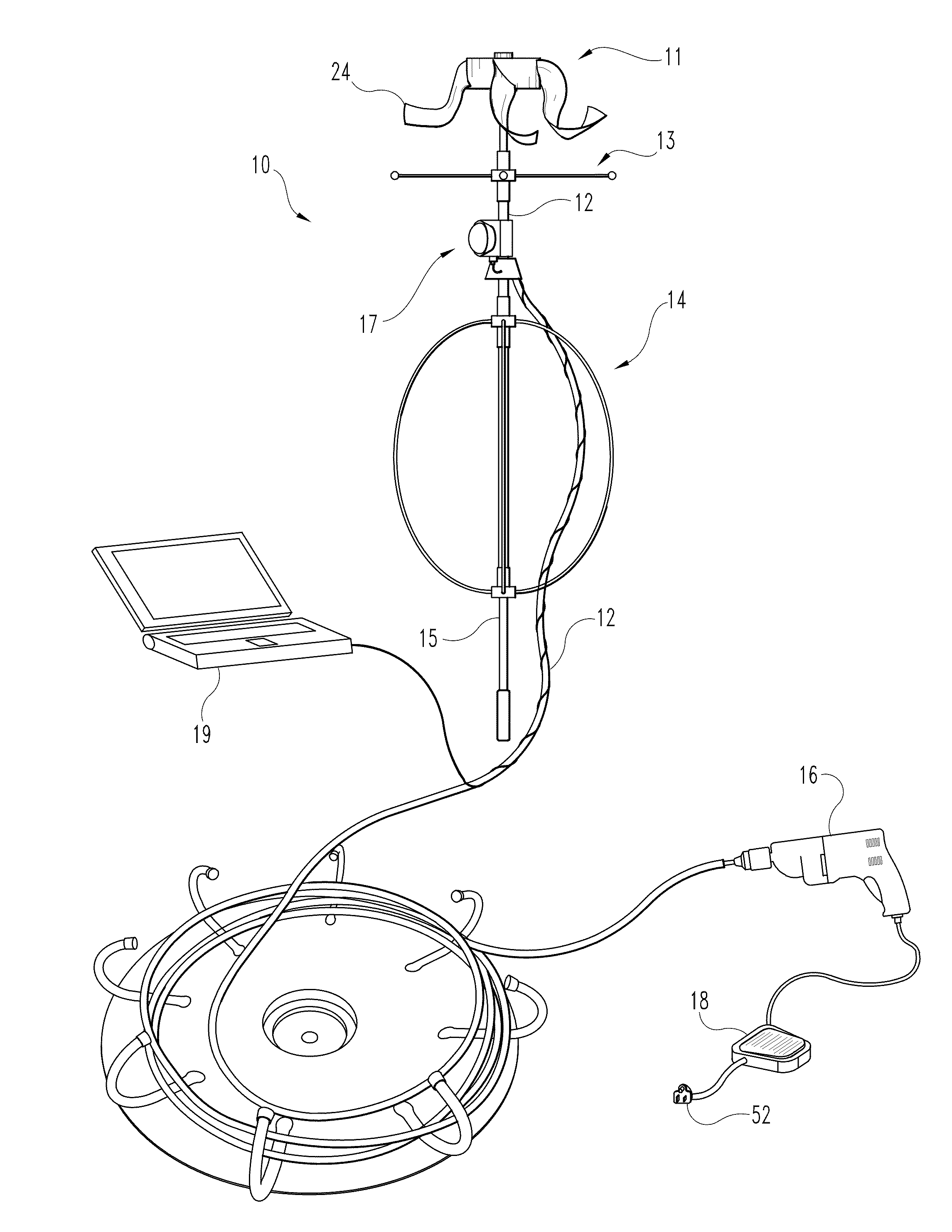
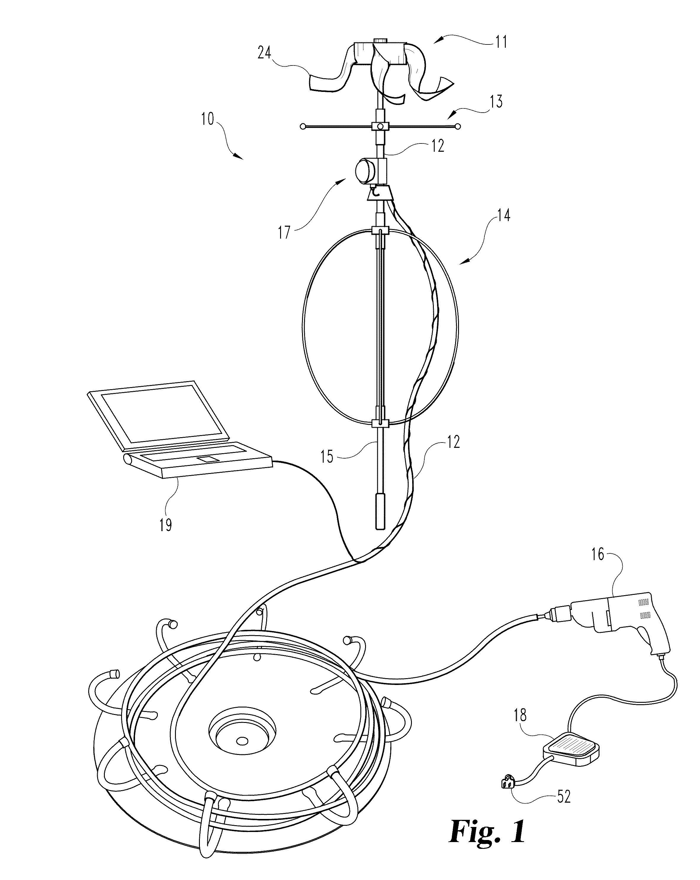
[0043]One aspect of the present invention provides a device for cleaning and remotely inspecting a chimney. The device includes a cleaning head that preferably comprises a hub with one or more cleaning arms attached thereto. A cable assembly is attached to the cleaning head. The cable assembly includes a flexible cable in a flexible casing, with the casing being sized and adapted to allow the cab...


PUM


Abstract

A device for cleaning a chimney preferably includes a cleaning head having a hub with brush arms extending from the hub, a cable assembly connected to the cleaning head and having a flexible cable surrounded by a casing, with the casing being sized to allow the cable to rotate in the casing without rotating the casing, at least one positioning assembly for holding the cleaning head a desired distance from the interior walls of a chimney, a motor attached to one end of the cable, and a positioning rod effective for pushing said cleaning head and cable assembly up a chimney for a distance of at least eight feet. A camera may be attached to the casing to allow observation and/or recording of the chimney while the cleaning head is working. The device may further include an air knife for dislodging debris when the device is used to sweep a chimney, and/or a vacuum for removing waste dislodged by the device. The motor may be a variable speed motor that is controlled by a foot switch to allow an individual chimney sweep to operate the cable, the rod, and the motor speed simultaneously.

Description

REFERENCE TO RELATED APPLICATIONS[0001]This application claims the benefit of U.S. Provisional Patent Application Ser. No. 61 / 124,358, filed Apr. 16, 2008, which is hereby incorporated by reference.FIELD OF THE INVENTION[0002]The present invention relates generally to devices for cleaning a chimney, and more particularly to a device for cleaning a chimney flue, optionally while simultaneously scanning the interior of the flue.BACKGROUND TO THE INVENTION[0003]For many years chimney sweeps have cleaned chimneys using brushes that attach to a series of rods that extend the length of the brush. More recently, sweeps have attempted to use a motor, such as a power drill motor, to spin the rods to improve cleaning efficiency. Unfortunately, this design has not proven satisfactory since the design of known chimney cleaning brushes does not prevent the bristle ends from getting caught between gaps between flue tiles. This can cause injury to the operator if the spinning rods are suddenly sto...

Claims


Application Information

Patent Timeline
Patent Type & Authority Applications(United States)
IPC IPC(8): B08B9/02
CPCF23J2213/60F23J3/026
Inventor MEREDITH, JOHN E.URBAN, THOMAS J.
Owner MEREDITH JOHN E
Why Eureka
Try Eureka