Heat sink base plate with heat pipe

a heat sink and heat pipe technology, applied in the field of heat sinks, can solve the problems of limited heat removal ability of heat sinks utilizing heat pipes, unsuitable applications, and relatively high cost, and achieve the effect of higher thermal resistan

Active Publication Date: 2009-10-22
AAVID THERMALLOY LLV
View PDF36 Cites 54 Cited by
  • Summary
  • Abstract
  • Description
  • Claims
  • Application Information

AI Technical Summary

Benefits of technology

[0012]According to the invention, a base plate for a heat sink is provided with an open channel in one surface, cooling fins on the opposite surface, and a heat pipe arrangement nested in the channel. The channel has at least one first or remote region with a first width, and a second or central region having a second width which is greater than the first width. The heat pipe arrangement has at least two evaporator sections juxtaposed side by side in the central region of the channel, and two condenser sections in respective remote regions of the channel. The evaporator sections are brought into direct contact with an object to be cooled, typically a CPU, so that the higher thermal resistance offered by an intervening metal plate is eliminated.
[0014]By having multiple evaporator sections juxtaposed in the central region of the channel, and multiple condenser sections in respective remote regions of the channel, thermal characteristics allowing heat spreading comparable to that of a vapor chamber are obtained, while allowing multiple cost, weight, and performance trade-offs, e.g. the use of lighter and less costly aluminum in place of copper for the base plate.
[0015]Heat transfer in the evaporator sections is maximized by providing the central region of the channel with a rectangular cross-section, and flattening the heat pipe sections in this region so that they have a rectangular profile with a collective width which is the same as the width of the central region of the channel.
[0016]According to another aspect of the invention, the portions of the heat pipe in the central region are coplanar with the bottom surface of the base plate, whereas the portions of the heat pipe in the remote regions are recessed from the bottom surface. This assures that the machining operation which is performed to achieve coplanarity of the evaporator sections cannot render the tubing wall too thin in other areas, which could cause leakage at an imperfection in the grain structure. The thinner wall section of the heat pipes produced by machining the exposed surfaces of the evaporator sections also improves the efficiency of the device, because the effective thermal conductivity of the evaporating fluid is vastly higher than that of metal. For example, while copper has a thermal conductivity of 380 W / m-° K., evaporating water has an effective thermal conductivity in excess of 10,000 W / m-° K. Thus, reducing the wall thickness of the heat pipe, which is typically about 0.5 mm, by up to 50%, further improves the rate of heat transfer from the CPU to the fluid.

Problems solved by technology

This is a relatively high profile design which is not suitable for applications where space above the mounting surface is limited.
In general, heat sinks utilizing heat pipes are limited in their heat removal ability, because the fluid has only one path returning to the evaporator along the length of the pipe, and the heat source is only partially covered by the evaporator section.
Vapor chambers can spread the heat generated by high power components over a large area of the base plate, but are relatively expensive, less robust structurally, and difficult to seal.
While heat sinks having heat pipes with evaporator sections covering the heat sink are known (US 2007 / 0074857), the amount of metal interposed between the vaporizing fluid and the object to be cooled offers higher than optimal thermal resistance and therefore worse performance.

Method used


Image

  • Heat sink base plate with heat pipe
  • Heat sink base plate with heat pipe
  • Heat sink base plate with heat pipe

Examples


Embodiment Construction

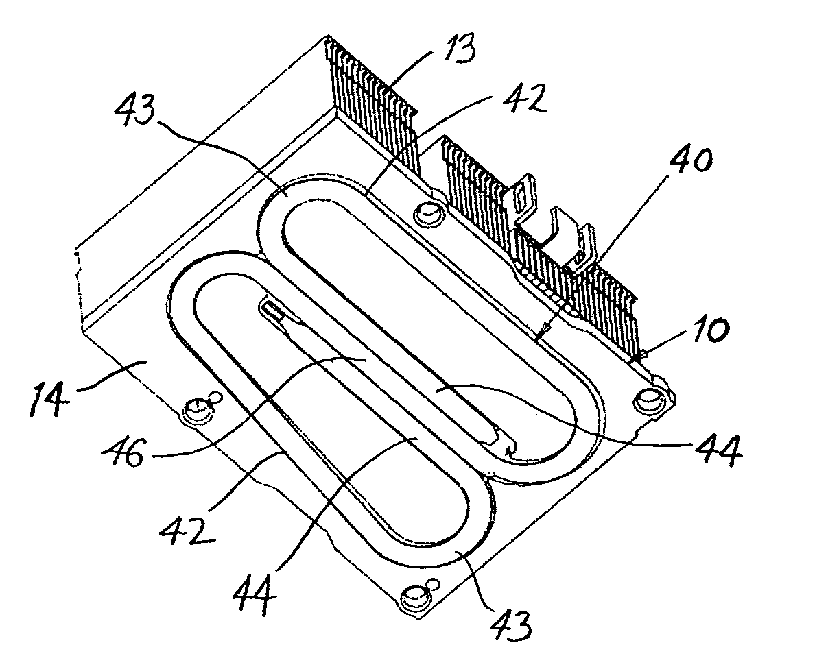
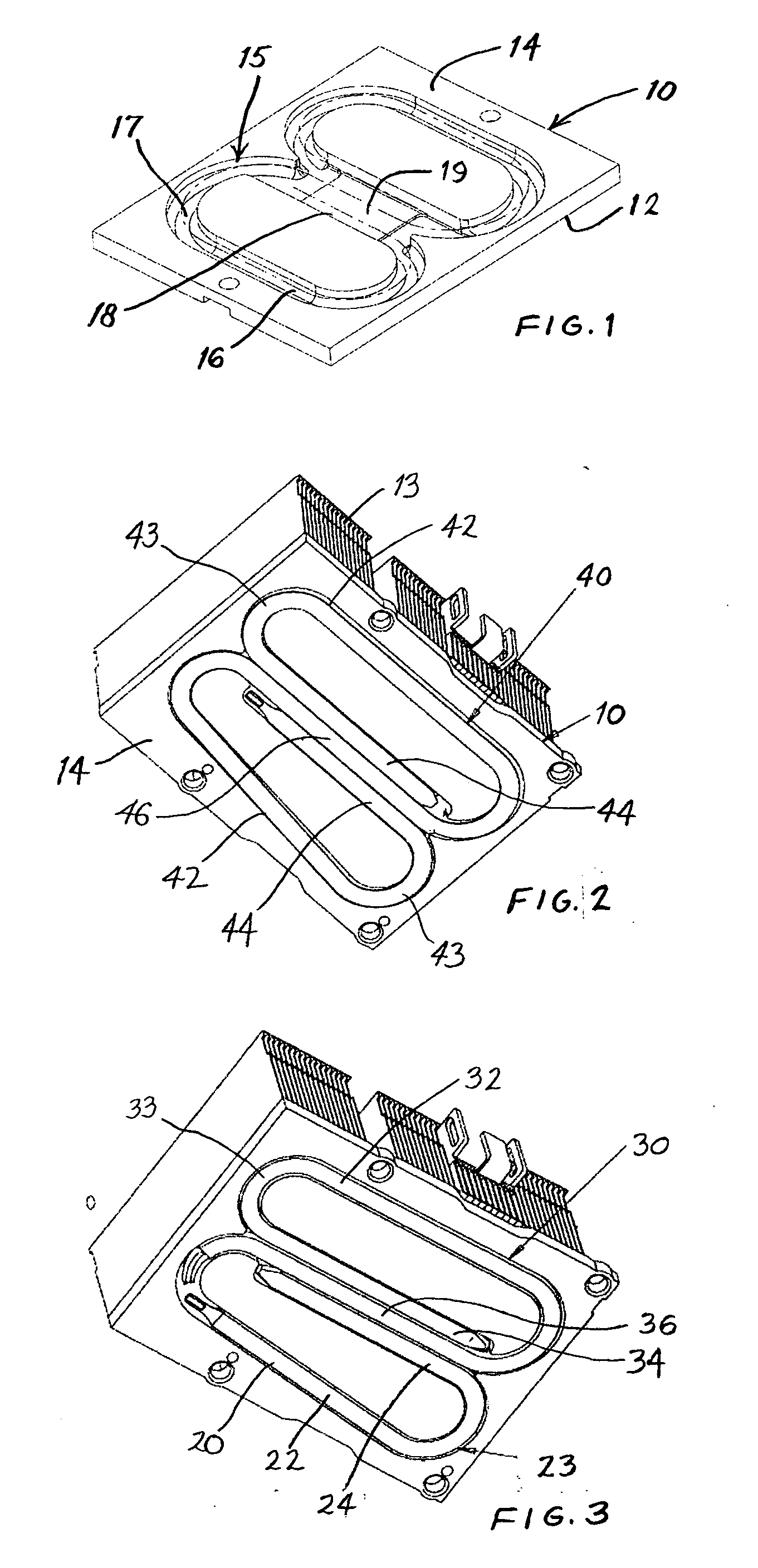
[0028]FIG. 1 shows a copper base plate 10 which is inverted so that its top surface 12 faces down and the opposed bottom surface 14 faces up. These surfaces are designated as “top” and “bottom” because the bottom surface would generally be placed over an element to be cooled, such as an IC chip on a circuit board. However it will be understood that the plate 10 can also be mounted against a chip on a vertical surface or even on the underside of a circuit board. In every case, it is intended that the bottom surface 14 is in contact with the element to be cooled.

[0029]The top surface 12 is provided with cooling fins 13, which are omitted here but shown in FIG. 2. The bottom surface 14 has a channel 15 with first or remote regions 16 having a floor 17, and a second or central region 18 having a floor 19, where the floor 19 is raised with respect to the floor 17. As shown in this view, the channel 15 has an overall shape resembling two ovals which are siamesed to form a central region 1...


PUM

PropertyMeasurementUnit
widthaaaaaaaaaa
shapeaaaaaaaaaa
volumeaaaaaaaaaa

Abstract

A heat sink assembly includes a base plate having a top surface provided with cooling fins, and a bottom surface with an open channel, the channel having remote regions and a central region with a rectangular cross-section. A heat pipe arrangement including at least two sections is nested in the channel, each section having at least one evaporator section and a condenser section, wherein the evaporator sections are juxtaposed side by side in the central region, and the condenser sections are in respective remote regions. The arrangement is preferably a single S-shaped heat pipe with a pair of hooked ends and a center section which form the evaporator sections, the evaporator sections each having a rectangular profile and an exposed surface which is flush with the bottom surface of the base plate, the condenser sections connecting the evaporator sections and being recessed below the bottom surface.

Description

BACKGROUND OF THE INVENTION[0001]1. Field of the Invention[0002]The invention relates to a heat sink of the type having base plate and a heat pipe with a flat surface which is brought into contact with a device to be cooled, such as a central processing unit (CPU).[0003]2. Description of the Related Art[0004]Heat sinks utilizing heat pipes are well known. A heat pipe generally consists of a tube forming a closed volume containing a heat transfer fluid which is present in two phases. The tube is preferably lined with a wicking material which distributes the liquid phase within the closed volume, and in particular draws it from a condenser section back toward an evaporator section. The condenser section is generally in contact with cooling fins or other means for removing heat, while the evaporator section is in contact with the device to be cooled.[0005]U.S. Pat. No. 7,059,391 discloses a heat sink utilizing a base plate having a pair of slots in which the ends of a heat pipe are rec...

Claims


Application Information

Patent Timeline
Patent Type & Authority Applications(United States)
IPC IPC(8): F28D15/04F28D15/02B21D53/02
CPCB21D53/02Y10T29/49353F28D15/0275F28D15/0233
Inventor WHITNEY, BRADLEY R.KANG, SUKHVINDER S.
Owner AAVID THERMALLOY LLV
Why Eureka
Try Eureka