
Boil Cooling Method, Boil Cooling Apparatus, Flow Channel Structure and Applied Product Thereof

a technology of flow channel structure and boil cooling, which is applied in the direction of heat exchange apparatus safety devices, lighting and heating devices, and semiconductor/solid-state device details, etc., to achieve compact operation and high heat flux cooling

Inactive Publication Date: 2009-10-22
TOKYO UNIVERSITY OF SCIENCE
View PDF9 Cites 8 Cited by
  • Summary
  • Abstract
  • Description
  • Claims
  • Application Information

AI Technical Summary

Benefits of technology

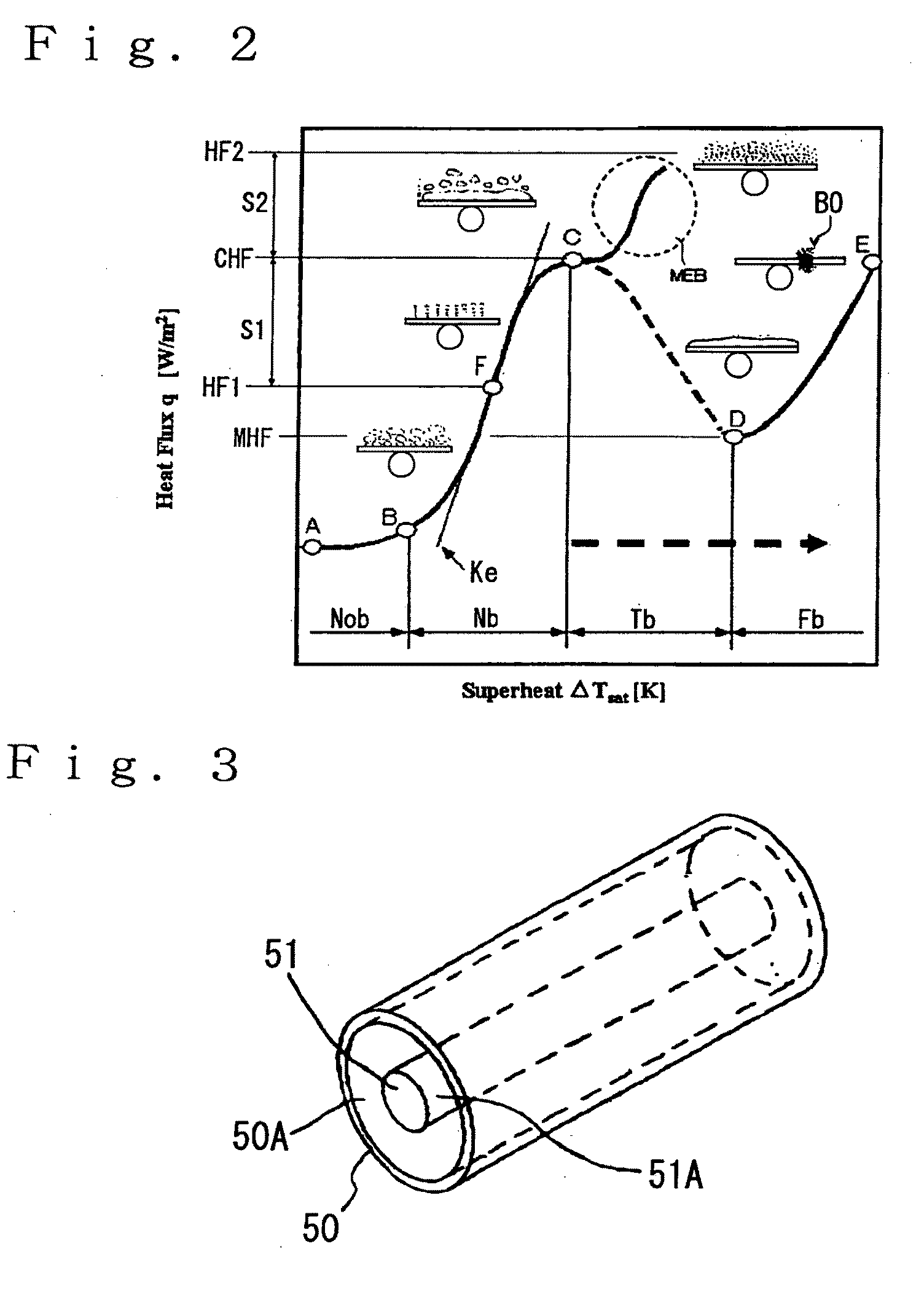
[0097]“The group of rigid needles” used in the present invention means a group composed of a plurality of rigid needles fixed to and provided on the inner wall portion of the tubular flow channel and having a function of reducing an air pressure generated upon collapse as a means for dividing the collapse of the bubble.
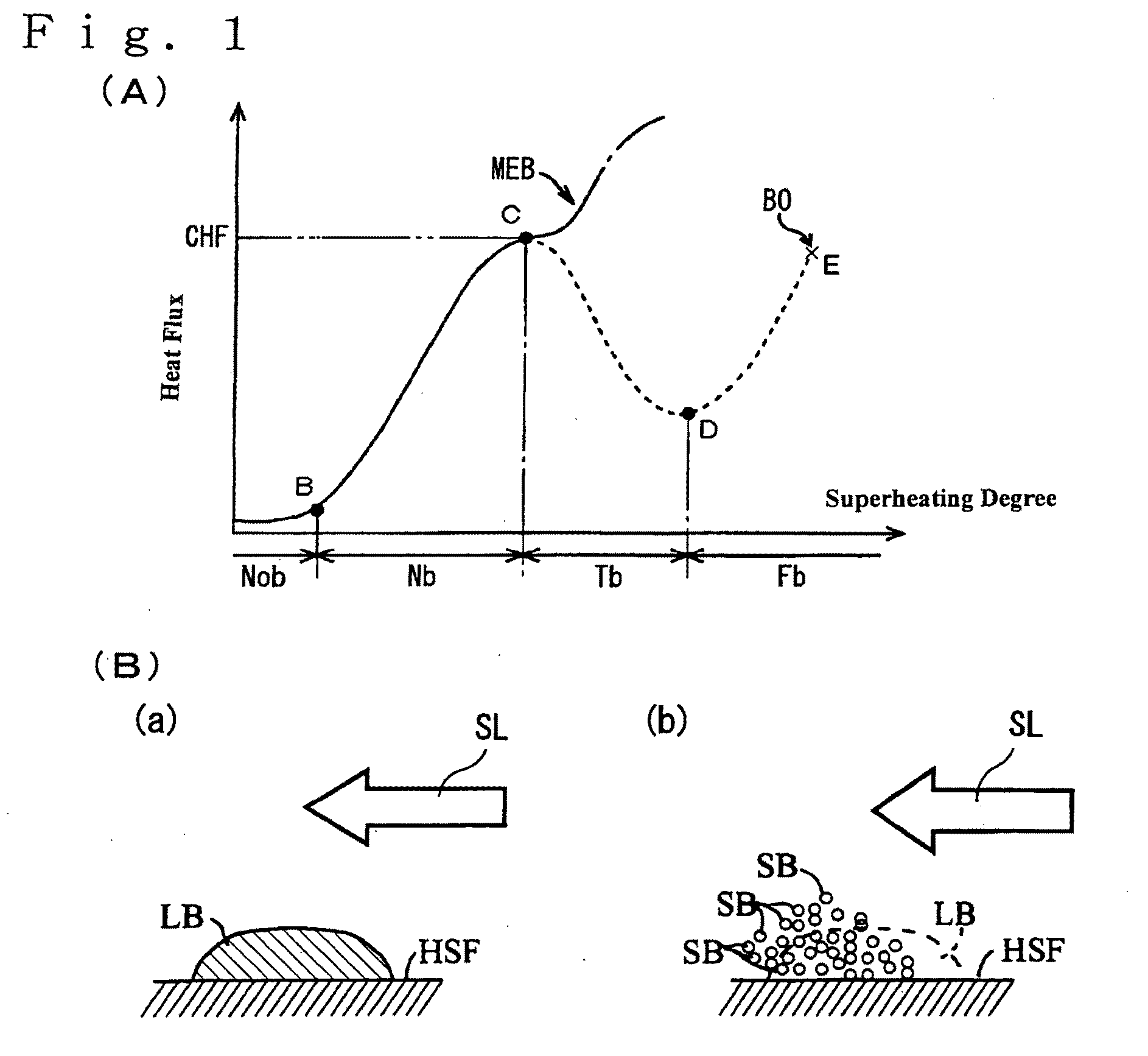
[0221]As described above, according to the present invention, there can be provided boil cooling methods and apparatus, flow channel structures and applied products, which have heretofore been available. Since the cooling by microbubble emission boiling is conducted in the boil cooling methods of the present invention, good boil cooling can be realized even in “an unstable region that becomes transition boiling according to a conventional boil cooling method”, and vibration and noise characteristic of the cooling by microbubble emission boiling can be extremely effectively lightened, so that vibration and noise of the boil cooling apparatus and applied products equipped with this apparatus can be effectively reduced by 60% or more. The lowering of heat flux on the downstream side of the cooling liquid can also be effectively lightened or prevented.

Problems solved by technology

As a result, it has been confirmed that when the condition of noise and vibration is observed, rapid increase in vibration or pressure occurs periodically and just after collapse of a coalesced bubble, and a high air pressure is generated when the whole coalesced bubble is collapsed at a time, which forms a cause of noise and vibration, and experiments have been conducted repeatedly.

Method used


Image

  • Boil Cooling Method, Boil Cooling Apparatus, Flow Channel Structure and Applied Product Thereof
  • Boil Cooling Method, Boil Cooling Apparatus, Flow Channel Structure and Applied Product Thereof
  • Boil Cooling Method, Boil Cooling Apparatus, Flow Channel Structure and Applied Product Thereof

Examples


experimental example 1

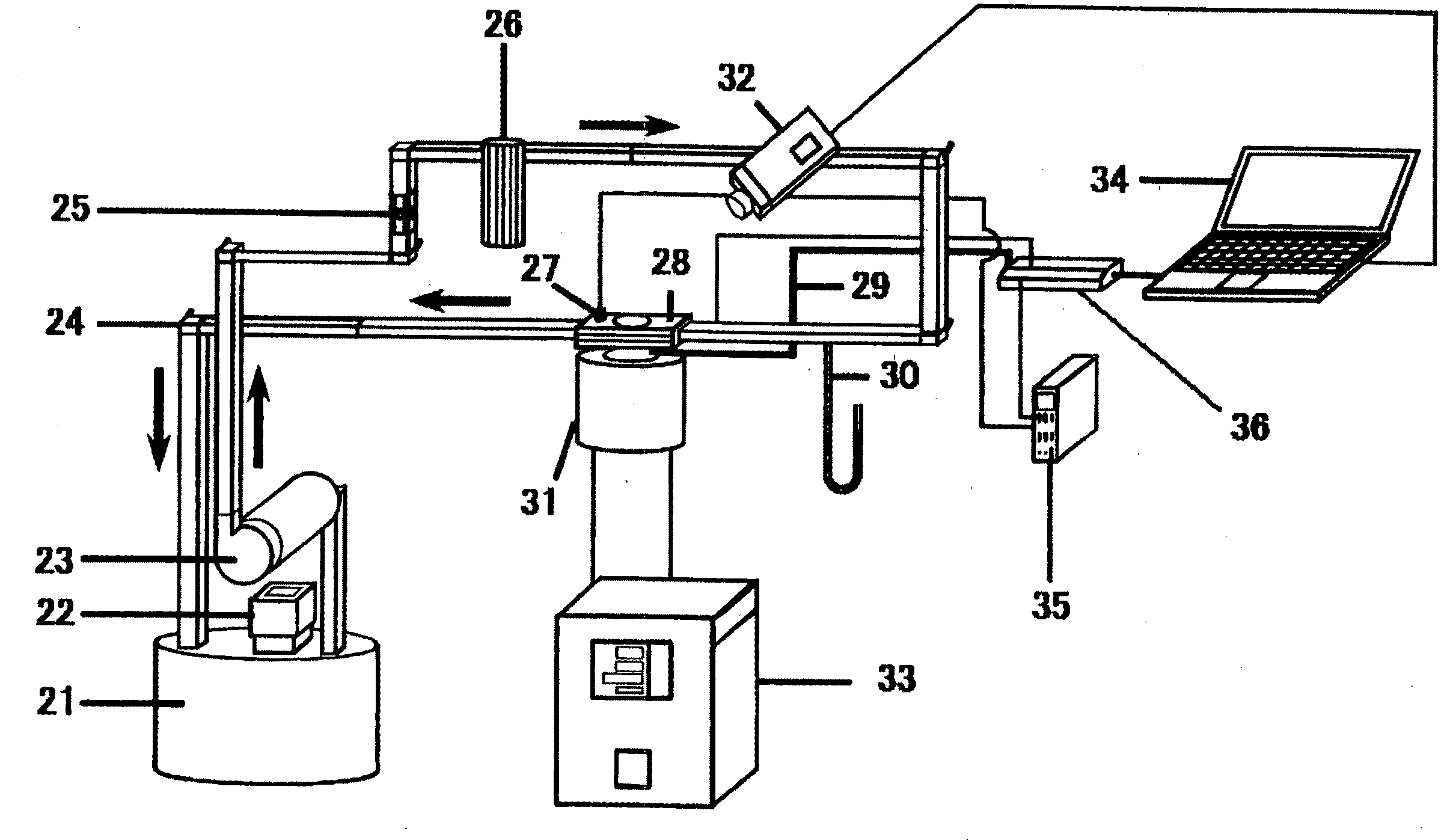
[0251]FIG. 9 and FIG. 10 are typical cross-sectional views of flow channel structures according to the present invention. The present inventors made a flow channel structure on the basis of these typical views to prove the vibration and noise-inhibiting effect by the group of rigid needles.

[0252]The experiment using this flow channel structure is based on finding a temperature of a heat-transfer surface and a heat removal heat flux from a temperature distribution and a temperature gradient of a thermocouple embedded in a pair of rectangular heat-transfer blocks.

[0253]This flow channel structure will be first described.

[0254]In FIG. 9, character 10 indicates a high heat-generating body that is “an object to be cooled”. The high heat-generating body 10 was made of copper, a peripheral portion of an upper flat surface thereof was cut out, a heat insulating material 11A and heat-resistant silicon 11B were provided at this portion, and the remaining portion was used as a surface 10A to b...

experimental example 2

[0284]An experiment of microbubble emission boiling was conducted under the same conditions as in Experimental Example 1 except that the mean flow rate was changed to 0.3 m / sec, the same 5 flow channel structures as those used in Experimental Example 1 of the flow channel structure having no group of rigid needles and those, in which the number (M) of rows of the group of rigid needles are 1, 3, 5 and 7, were used.

[0285]As a result, it was confirmed that even when the row of rigid needles is increased, the maximum heat flux retains a value within a range of about 350 to 450 W / cm2 and does not vary according to the number of rigid needles.

[0286]On the other hand, the pressure generated by collapse of the coalesced bubble is reduced as the row of rigid needles is increased, and the maximum momentary pressure P is reduced to about 310 kPa (77%) when the group of rigid needles is provided in a row compared with about 400 kPa when no group of rigid needles is provided, and sequentially r...

experimental example 3

[0290]An experiment of microbubble emission boiling was conducted under the same conditions as in Experimental Example 1 except that the cooling liquid was changed to a cooling liquid having a subcooling degree of 20 K, the same 5 flow channel structures as those used in Experimental Example 1 of the flow channel structure having no group of rigid needles and those, in which the number (M) of rows of the group of rigid needles are 1, 3, 5 and 7, were used.

[0291]As a result, it was confirmed that even when the row of rigid needles is increased, the maximum heat flux retains a value within a range of about 300 to 400 W / cm2 and does not vary according to the number of rigid needles.

[0292]On the other hand, with respect to the pressure generated by collapse of the coalesced bubble, the maximum momentary pressure P is reduced to about 190 kPa (50%) when the group of rigid needles is provided in a row compared with about 380 kPa when no group of rigid needles is provided, and reduced to a...


PUM

PropertyMeasurementUnit
Temperatureaaaaaaaaaa
Lengthaaaaaaaaaa
Lengthaaaaaaaaaa

Abstract

The invention provides a boil cooling method, a boil cooling apparatus, a flow channel structure, and applied products thereof, by which noise and vibration attending on cooling by microbubble emission boiling can be effectively reduced, and efficient boil cooling can be realized.A subcooled cooling liquid is caused to flow through a flow channel structure, which is formed by using a surface of an object 10 to be cooled as a surface 10A to be cooled and the surface 10A to be cooled as a tubular wall and has a tubular flow channel 16, through which the subcooled cooling liquid is caused to flow, and a structure that a group of rigid needles N1, N2, . . . Ni . . . is protruded within the tubular flow channel 16 from the tubular wall of the tubular flow channel, thereby conducting cooling by microbubble emission boiling.

Description

TECHNICAL FIELD[0001]The present invention relates to a boil cooling method, a boil cooling apparatus for carrying out the boil cooling method, a flow channel structure used in this boil cooling apparatus, and applied products to which these method, apparatus and structure are applied.BACKGROUND ART[0002]When a liquid is heated, its temperature is gradually raised and lastly reached “a saturation temperature” that the liquid temperature does not rise any more. When the liquid is further heated, “vaporization of the liquid” occurs in the interior of the liquid. This state is called boiling, and the saturation temperature is called a boiling point.[0003]The liquid temperature is raised in the boiled state, and the energy applied to the liquid by the heating is consumed for “vaporization of the liquid in the interior of the liquid”. This thermal energy is called “latent heat”. The latent heat is extremely large compared with the thermal energy for raising the temperature of the liquid....

Claims


Application Information

Patent Timeline
IPC IPC(8): F28D15/00B60K6/20
CPCF28D15/02F28D15/0266F28F1/40H01L23/427H01L23/44H05K7/20936H01L2924/0002F28F2245/02F28F2265/28F28F2265/30H01L2924/00
Inventor SUZUKI, KOICHIGOTO, YOSUKE
Owner TOKYO UNIVERSITY OF SCIENCE
Learn More