Semiconductor light emitting device and method for fabricating the same
a technology of semiconductors and light emitting devices, which is applied in the direction of semiconductor devices, basic electric elements, electrical appliances, etc., can solve the problems of low red emission spectrum, low color rendering property, and insufficient excitation efficiency of red fluorescent materials, so as to suppress the occurrence of cracks in semiconductor films, reduce stress in semiconductors, and improve the effect of reproducibility
- Summary
- Abstract
- Description
- Claims
- Application Information
AI Technical Summary
Benefits of technology
Problems solved by technology
Method used
Image
Examples
embodiment 1
[0126]A first embodiment of the present invention will be described with reference to the drawings.
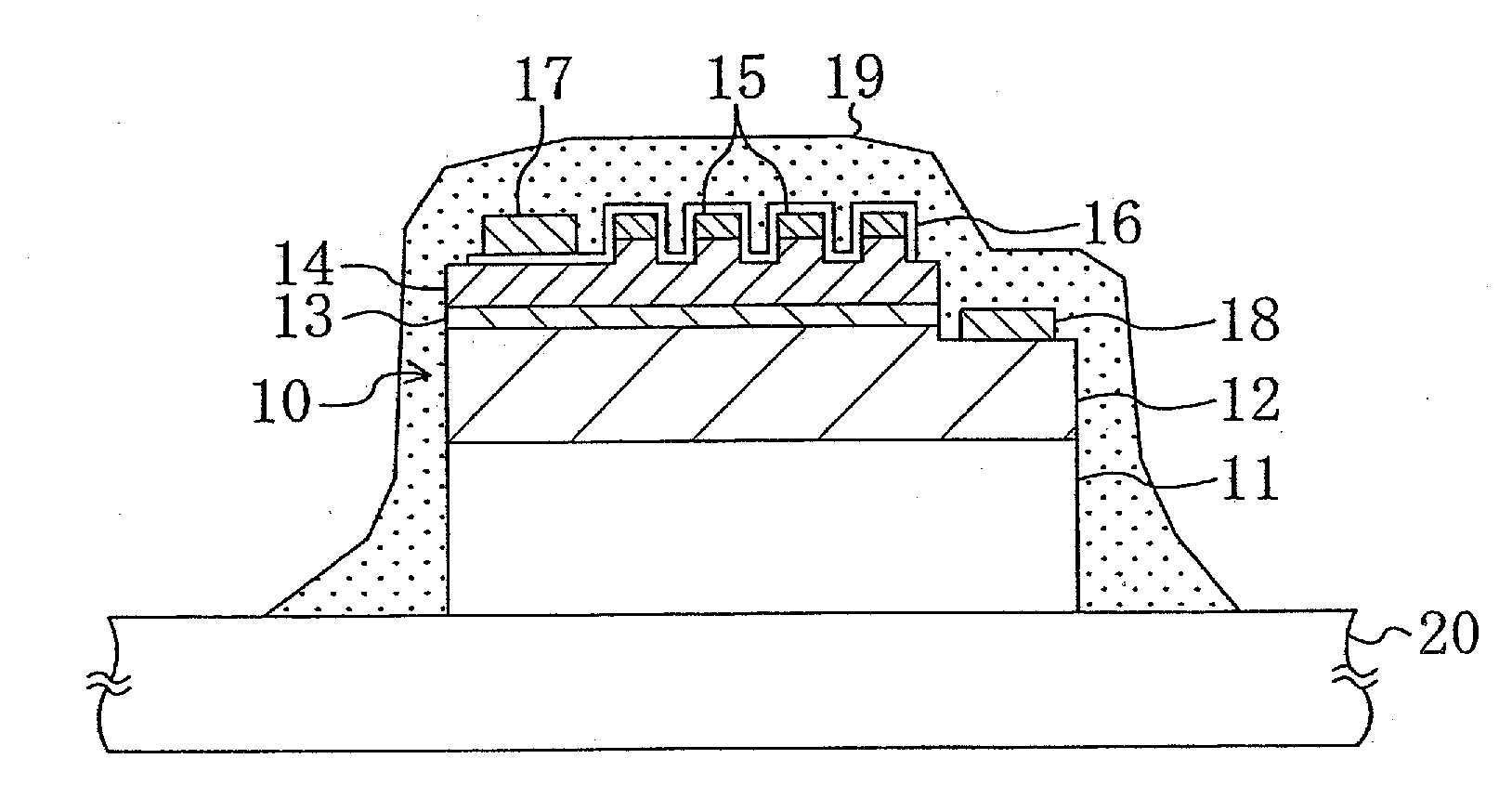
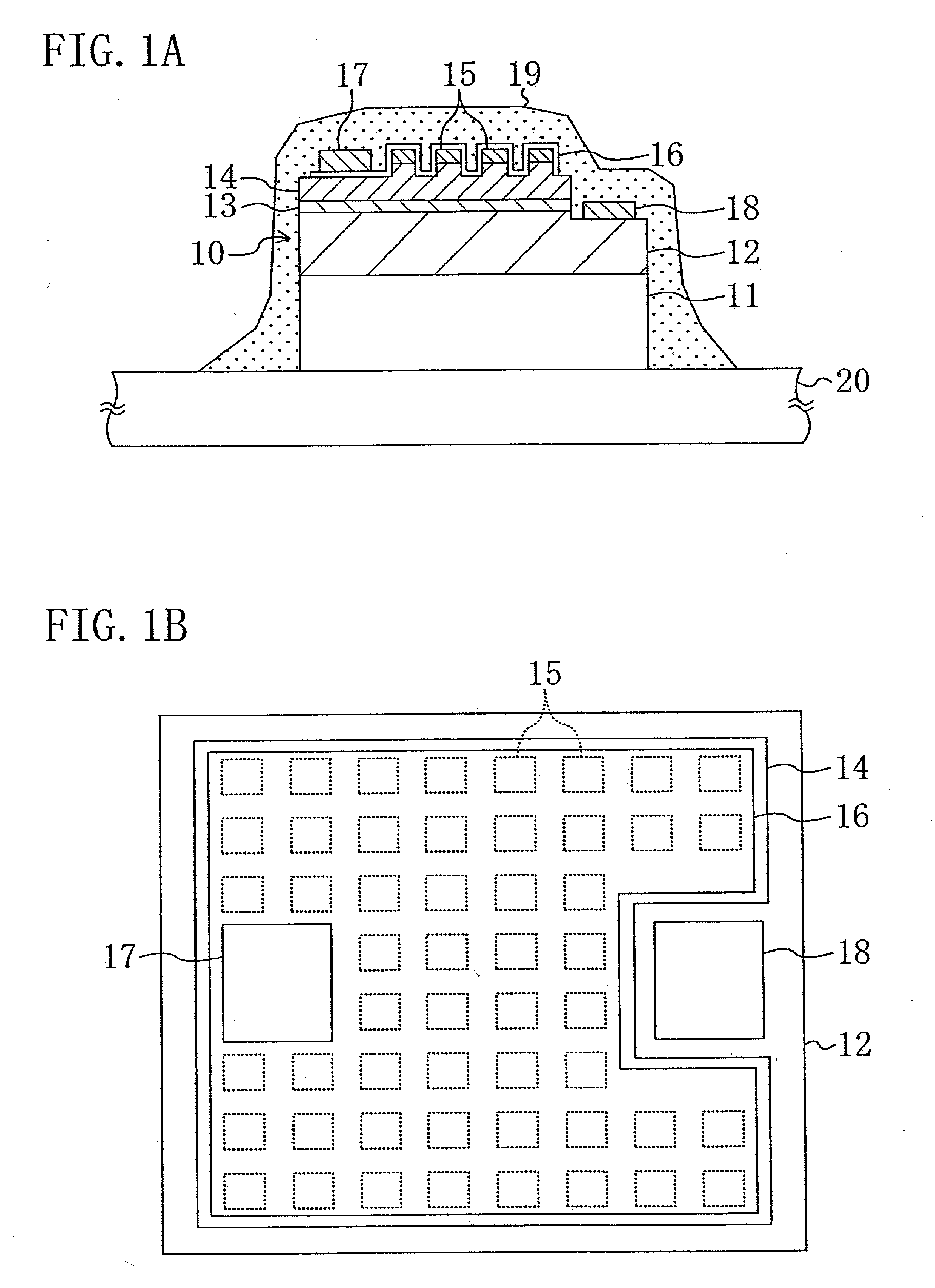
[0127]FIG. 1A shows a cross-sectional structure of a semiconductor light emitting device according to the first embodiment and FIG. 1B shows a plan structure thereof.
[0128]As shown in FIGS. 1A and 1B, a semiconductor light emitting device according to the first embodiment is composed of: a blue light emitting diode 10 mounted at a specified position on a package 20 as a mounting member; a red light emitting layer 15 grown epitaxially on the blue light emitting diode 10; and an insulating material 19 containing an yttrium aluminum garnet (YAG) fluorescent material. In FIG. 1B, the depiction of the insulating material 19 is omitted.
[0129]The blue light emitting diode 10 is composed of: an n-type semiconductor layer 12 made of n-type GaN; an active layer 13 having a multiple quantum well structure made of InGaN; and a p-type semiconductor layer 14 made of p-type Al0.05Ga0.95N which are ep...
embodiment 2
[0153]A second embodiment of the present invention will be described with reference to the drawings.
[0154]FIG. 5 shows a cross-sectional structure of a semiconductor light emitting device according to the second embodiment. The description of the components shown in FIG. 5 which are the same as those shown in FIG. 1A will be omitted by retaining the same reference numerals.
[0155]As shown in FIG. 5, the blue light emitting diode 10 in which the red light emitting layer 15 is formed selectively on the p-type semiconductor layer 14 is mounted by so-called flip-chip mounting such that the red light emitting layer 15 is opposed to the mounting surface of the package 20.
[0156]The p-type semiconductor layer 14 and the red light emitting layer 15 are connected electrically to the p-side electrode pad (not shown) of the package 20 by the p-side electrode 17 made of a multilayer film of platinum (Pt) and gold (Au) and a first bump 22 made of silver. On the other hand, the n-side electrode 18 ...
embodiment 3
[0160]A third embodiment of the present invention will be described with reference to the drawings.
[0161]FIG. 6A shows a cross-sectional structure of a semiconductor light emitting device according to the third embodiment and FIG. 6B shows a plan structure thereof. The description of the components shown in FIGS. 6A and 6B which are the same as those shown in FIGS. 1A and 1B will be omitted by retaining the same reference numerals.
[0162]As shown in FIGS. 6A and 6B, the semiconductor light emitting device according to the third embodiment is composed of: the blue light emitting diode 10 mounted at a specified position on the package 20 as a mounting member; the red light emitting layer 15 grown epitaxially on the blue light emitting diode 10; and the insulating material 19 containing an yttrium aluminum garnet (YAG) fluorescent material.
[0163]The third embodiment is different from the first embodiment in that the transparent electrode 16 made of ITO covers only the upper surface of t...
PUM
 Abstract
Description
Claims
Application Information
 - R&D
- Intellectual Property
- Life Sciences
- Materials
- Tech Scout
- Unparalleled Data Quality
- Higher Quality Content
- 60% Fewer Hallucinations
Browse by: Latest US Patents, China's latest patents, Technical Efficacy Thesaurus, Application Domain, Technology Topic, Popular Technical Reports.
© 2025 PatSnap. All rights reserved.Legal|Privacy policy|Modern Slavery Act Transparency Statement|Sitemap|About US| Contact US: help@patsnap.com


