High-Voltage Light Emitting Diode Circuit Having a Plurality of Critical Voltages and Light Emitting Diode Device Using the Same

a technology of light emitting diodes and critical voltages, which is applied in the direction of electroluminescent light sources, transportation and packaging, lighting and heating apparatus, etc., can solve the problems of increasing the manufacturing cost of led illumination equipment, inconvenient use, and the inability to use whole equipment, so as to reduce the manufacturing cost of the illumination device

Inactive Publication Date: 2009-10-22
TOP CRYSTAL TECH
View PDF4 Cites 42 Cited by
  • Summary
  • Abstract
  • Description
  • Claims
  • Application Information

AI Technical Summary

Benefits of technology

[0019]3. The design of a plurality of critical voltages enables the LEDs to be activated according to the set critical voltages, and replaces the design of segmented control using switching circuits in the prior art, so as to reduce the manufacturing cost of the illumination device.

Problems solved by technology

In the current diode illumination products, when a series circuit design is adopted, the failure of one LED may cause that the whole equipment cannot be used, and the failed LED needs to be replaced with a new one, which is inconvenient in use.
If it intends to activate the LED illumination equipment segment by segment, an additional switching circuit needs to be designed for control, which may increase the manufacturing cost of the LED illumination equipment.
Although the LED circuit is applicable to a DC or AC power supply environment, it is a discrete component with a large size, and thus does not conform to the design trend toward light, thin, short, and small circuits.
Although the LED circuit is manufactured by a chip process and has a small volume, it can only be applied in an AC voltage environment.
Further, the LEDs having the same polarity are all serially-connected, so that when one of the LEDs fails, the other LEDs cannot be used any longer, which is also inconvenient in use.

Method used


Image

  • High-Voltage Light Emitting Diode Circuit Having a Plurality of Critical Voltages and Light Emitting Diode Device Using the Same
  • High-Voltage Light Emitting Diode Circuit Having a Plurality of Critical Voltages and Light Emitting Diode Device Using the Same
  • High-Voltage Light Emitting Diode Circuit Having a Plurality of Critical Voltages and Light Emitting Diode Device Using the Same

Examples


first embodiment

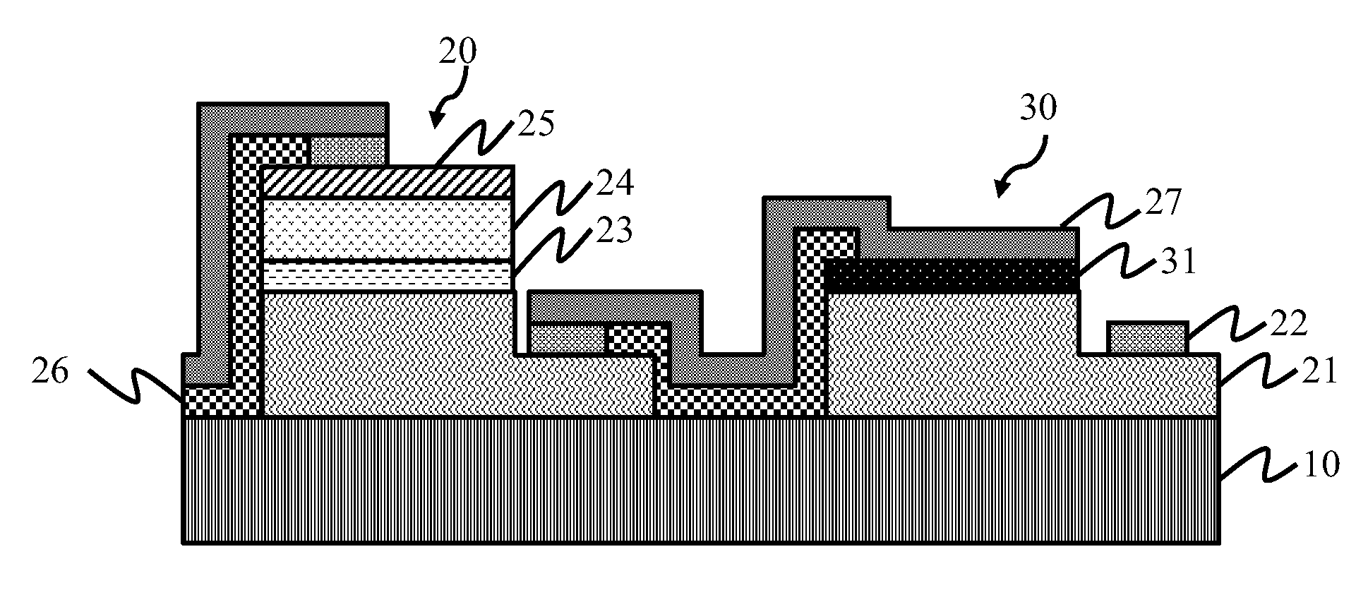
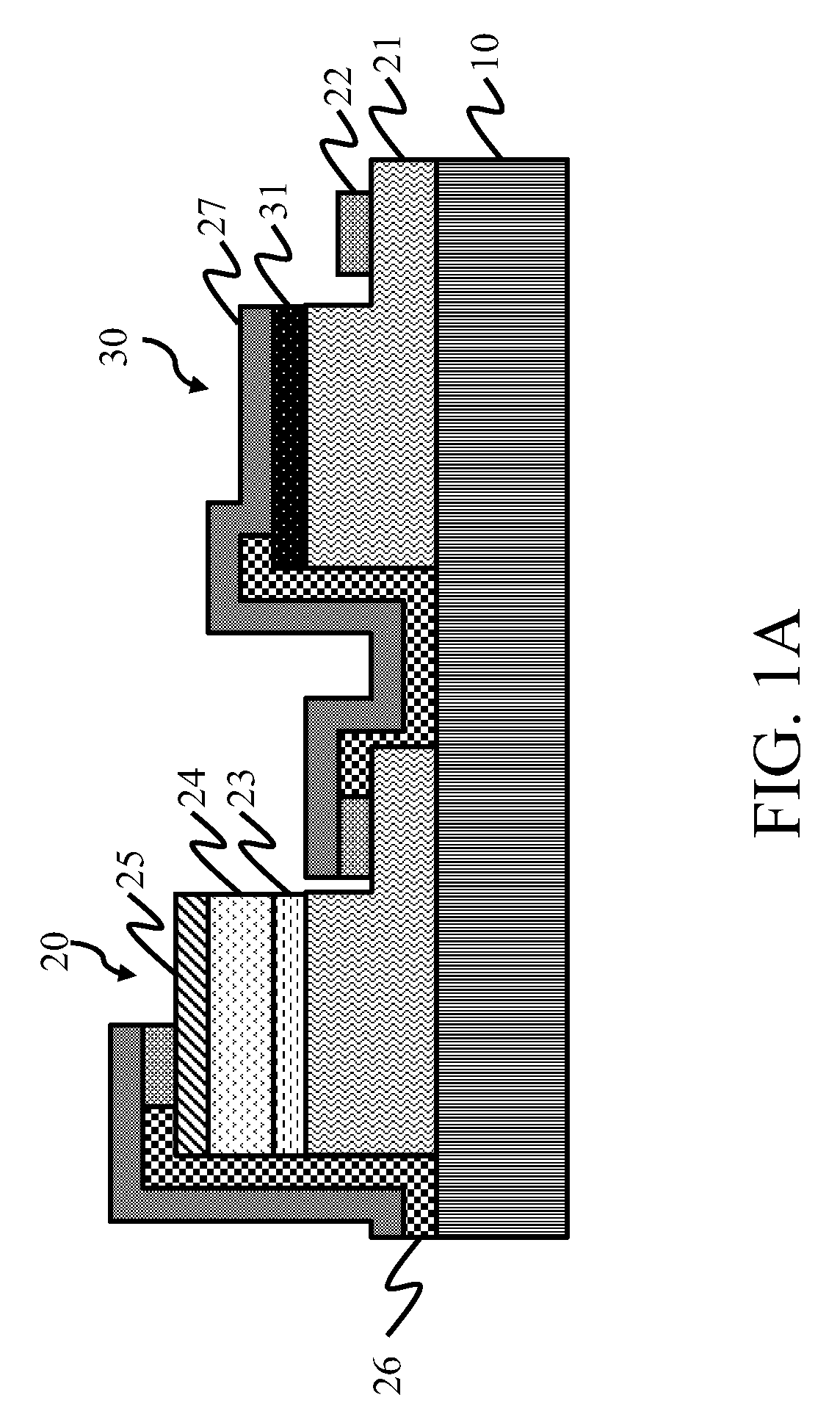
[0068]The high-voltage LED chip 100 having an impedance element (as the structure of the first embodiment in the present invention) comprises: a first substrate 10, fixed in the chip base 211; a first LED 20, formed on the first substrate 10, in which one end of the first LED 20 is electrically connected to the first lead frame 220 via a first wire 221; and an impedance element 30, formed on the first substrate 10, in which one end of the impedance element 30 is electrically connected in series with the other end of the first LED 20, and the other end of the impedance element 30 is electrically connected to the second lead frame 230 via a second wire 231. Particularly, the high-voltage LED chip 100 having an impedance element may be a combination of, but not limited to, red, blue, and green diode chips.

[0069]The light-receiving layer 240 is a transparent resin having a high light transmittance or a transparent colloid, and is covered on the high-voltage LED chip 100 having an impeda...

second embodiment

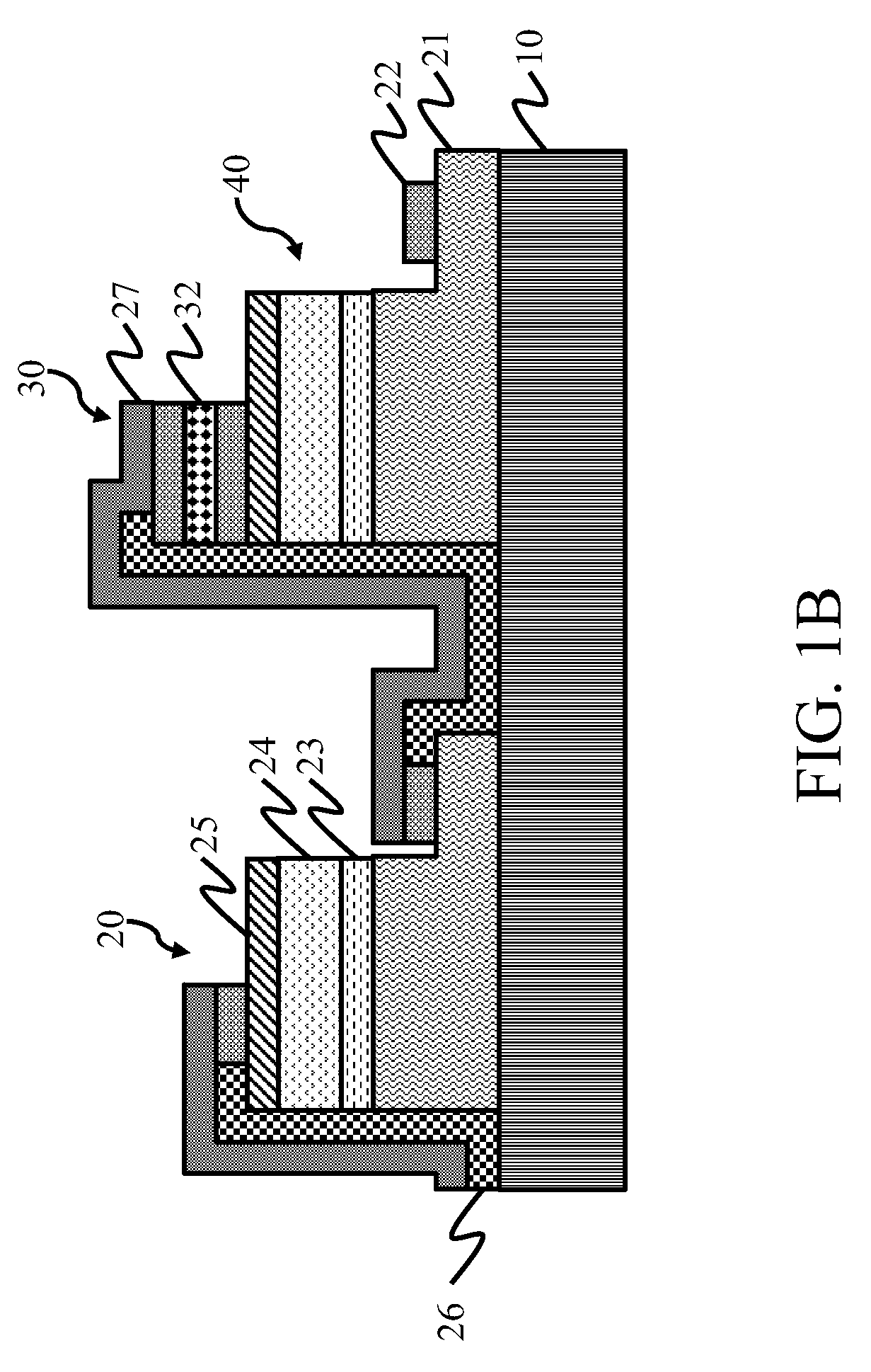
[0071]In addition, the high-voltage LED chip 100 having an impedance element further comprises at least a second LED 40 (as the structure of the second embodiment in the present invention). The second LED 40 is formed on the first substrate 10, has a polarity opposite to that of the first LED 20, and is connected in parallel with the first LED 20, such that the high-voltage LED chip 100 having an impedance element may be operated in an AC power supply environment.

eighth embodiment

[0072]FIG. 2B is a schematic cross-sectional view of an LED device according to the present invention. The LED device comprises a base structure 200, a submount high-voltage LED chip 300, a light-receiving layer 240, and a lens 250.

[0073]The base structure 200 comprises a body 210, a first lead frame 220, and a second lead frame 230.

[0074]A chip base 211 is formed in the body 210 and is adapted to support the submount high-voltage LED chip 300.

[0075]The first lead frame 220 and the second lead frame 230 are made of a metal. The two lead frames, separated from each other and having no electrical connection, are fixed on the body 210.


PUM


Abstract

A high-voltage light emitting diode (LED) circuit having a plurality of critical voltages and an LED device using the same are described. The high-voltage LED circuit includes a first substrate, at least a first LED formed on the first substrate, and at least an impedance element formed on the first substrate and electrically connected in series with one end of the first LED. The first LED is connected in parallel with at least a second LED based on the characteristics of the impedance element, and the second LED has a polarity opposite to that of the first LED, such that the high-voltage LED circuit may be operated in an AC power supply environment, thereby improving the convenience of using the LEDs.

Description

CROSS-REFERENCE TO RELATED APPLICATIONS[0001]This non-provisional application claims priority under 35 U.S.C. § 119(a) on Patent Application No(s). 097114236 filed in Taiwan, R.O.C. on Apr. 18, 2008 the entire contents of which are hereby incorporated by reference.BACKGROUND OF THE INVENTION[0002]1. Field of Invention[0003]The present invention relates to a light emitting diode (LED) circuit and an LED device, and more particularly to a high-voltage LED circuit having a plurality of critical voltages and an LED device using the same.[0004]2. Related Art[0005]With the development of material technology, the color and brightness of the light emitted by the light emitting diode (LED) have made dramatic progress. Various LED display technologies focus on true color and high brightness. The LED has a great potential to become a new-generation illumination equipment for lighting people's life.[0006]In recent years, due to continuous improvement of the luminous efficiency and other propert...

Claims


Application Information

Patent Timeline
Patent Type & Authority Applications(United States)
IPC IPC(8): B60Q1/00
CPCH01L25/167H01L27/15H01L27/153H01L2224/16H01L2924/3011H05B33/0806H01L2924/09701H01L33/385H05B45/30
Inventor CHOU, MING HUANG
Owner TOP CRYSTAL TECH
Why Eureka
Try Eureka