Device and method for determining the density of a fluid

a density and fluid technology, applied in the direction of liquid/fluent solid measurement, level indicator with buoyant probe, engine lubrication, etc., can solve the problems of inaccurate and unreliable, complex and expensive differential pressure sensor accuracy in the per mill range, not suitable for continuous measurement with changing levels or filling levels, etc., to improve the density-measuring device, improve the accuracy, and improve the accuracy

Inactive Publication Date: 2009-10-22
FAFNIR
View PDF9 Cites 13 Cited by
  • Summary
  • Abstract
  • Description
  • Claims
  • Application Information

AI Technical Summary

Benefits of technology

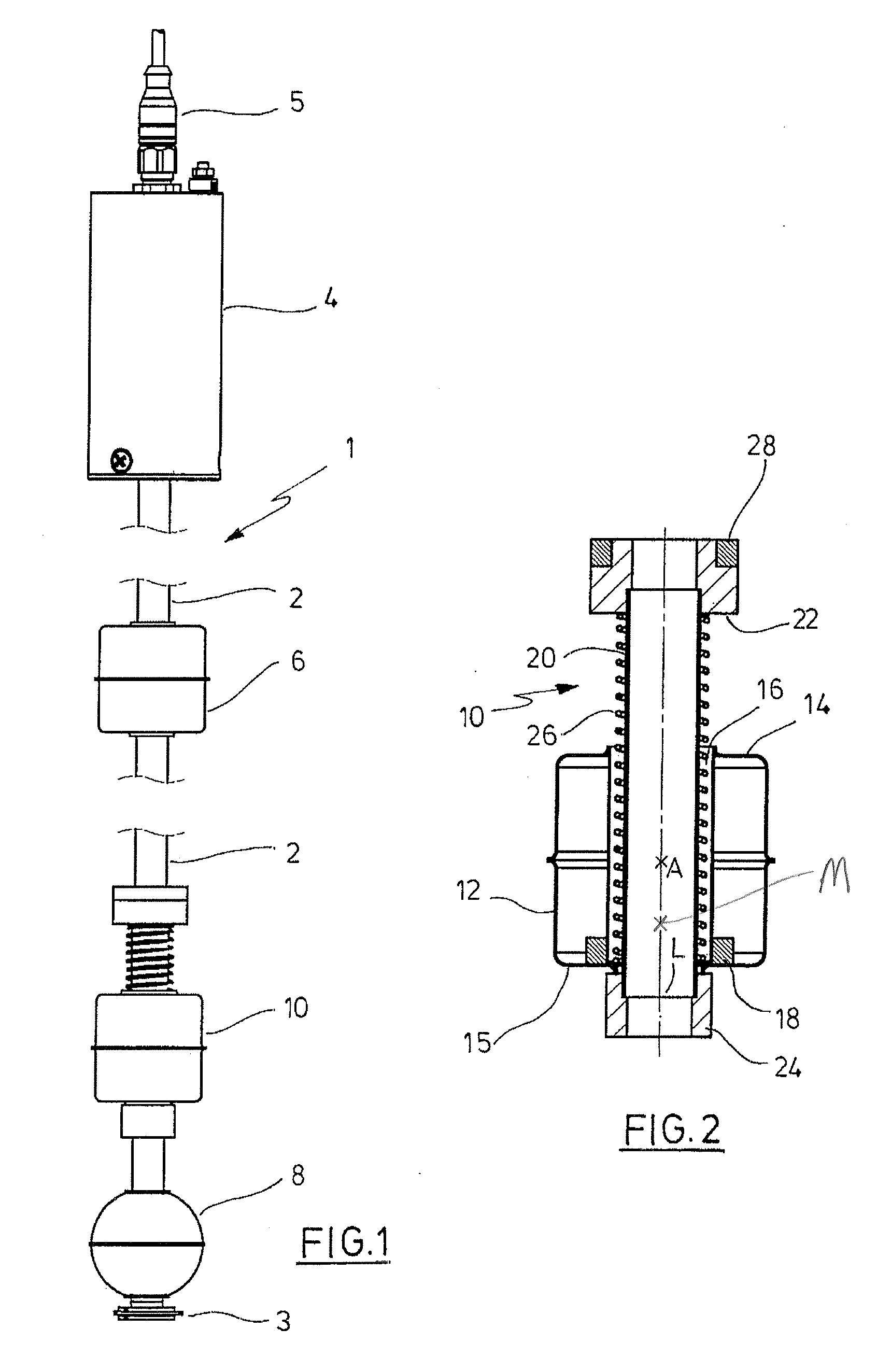
[0014]The object of the invention is therefore to improve the density-measuring devices which are previously known in particular from U.S. Pat. No. 5,471,873 and U.S. Pat. No. 5,253,522 and to provide a possible way of determining the density of a fluid in conjunction with a magnetostrictive position-measuring system with relatively little complexity and with a high degree of precision.

Problems solved by technology

Differential pressure sensors with the necessary accuracy in the per mill range are, however, very complex and expensive, in particular if they are to be used in explosion-protected areas, such as is necessary, for example, for a fuel filling station.
This is however inaccurate and unreliable.
A further method, which is also complex, is to determine the mass of a known volume of fluid from the oscillation of a resonator such as is utilized, for example, in the determination of density by Coriolis flow sensors.
Since an areometer does not become completely immersed in the fluid, it migrates with the filling level of the fluid in a reservoir container, which is not suitable for continuous measurement with changing levels or filling levels.
Since, in addition, in the case of density measurement using a buoyant body which operates counter to an elastic element, a state of equilibrium is reached between the buoyancy force, the force of gravity and the spring force, even small friction effects lead to hysteresis and to falsification of the measured values.
Furthermore, with the previously known arrangements a tilting moment is produced in the buoyant body even as a result of very small imbalances, and this leads to increased friction.

Method used


Image

  • Device and method for determining the density of a fluid
  • Device and method for determining the density of a fluid
  • Device and method for determining the density of a fluid

Examples


second embodiment

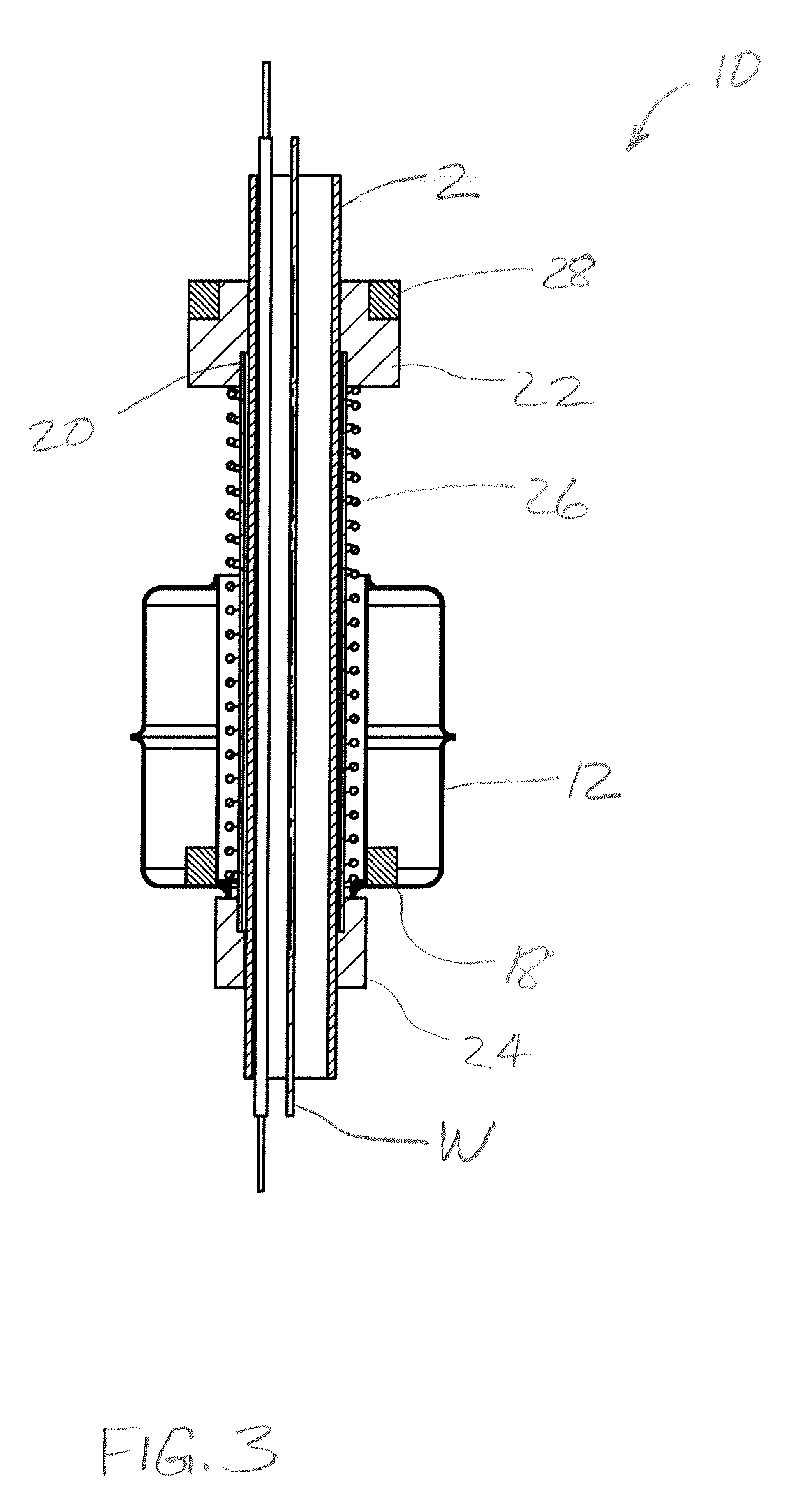
[0060]Turning to FIG. 4, an alternative density-determining device 30 is constructed in accordance with the present invention. In the alternative density-determining device 30, the top and bottom are essentially interchanged compared to the exemplary embodiment according to FIGS. 2 and 3. Furthermore, a buoyant body 32 is heavier so that it would not rise upward without support. However, the helical spring 34 presses from below so that an equilibrium of the explained type is established again, with the position of the magnet 36 (or the difference between the position of the magnet 36 and that of the reference magnet 38) being a measure of the density which is to be determined.

[0061]In the second embodiment, the buoyant body 32 must therefore also be able to move, and the spring 34 acts on the buoyant body 32 above the centre A of buoyancy. In addition, the magnet should be arranged in such a way that the centre of mass M of the buoyant body 32 is below the centre A of buoyancy of th...

third embodiment

[0062]Turning to FIG. 5, an alternative density-determining device 40 is constructed in accordance with the present invention. In the illustrated embodiment, the device 40 includes a plurality of buoyant bodies 42, a plurality of springs 44, and a plurality of magnets 46. The buoyant bodies 42, with assigned springs 44 and magnets 46, are arranged at different levels of the magnetostrictive position-measuring system of a storage tank. As discussed previously, this makes it possible to determine the density of the fuel at different levels. In addition, embodiments relating to the application possibilities, in particular in the region of a fuel filling station, can also be found there.


PUM

PropertyMeasurementUnit
densityaaaaaaaaaa
elastic deformationaaaaaaaaaa
buoyancy forceaaaaaaaaaa

Abstract

A device for determining the density of a fluid comprises a buoyant body, a spring which engages on the buoyant body and whose elastic deformation is a measure of the buoyancy force of the buoyant body, and a magnet which is designed to sense the elastic deformation of the spring by means of a magnetostrictive position-measuring system. The spring is compressively loaded and, if the buoyancy force of the buoyant body is greater than its weight, said spring acts on the buoyant body underneath its centre of buoyancy. The device is preferably used to determine the density of fuel, a magnetostrictive filling level measuring system which is present in a storage tank for fuel being used.

Description

CROSS REFERENCE TO APPLICATION[0001]German Application Serial No. 10 2006 033 237.7, filed Jul. 18, 2006 and European Application Serial No. 07008114.6, filed Apr. 20, 2007 are hereby incorporated in their entirety by reference herein.BACKGROUND[0002]1. Field[0003]The invention relates to a device and a method for determining the density of a fluid, in particular for determining the density of fuel in a storage tank, for example at a fuel filling station, in a tank farm or in a tanker motor vehicle. The density which is measured and determined in this way can be used in data management at fuel filling stations and for quality assurance. This is because the density of fluids is an important indicator for the determination of their quality.[0004]2. Discussion of Prior Art[0005]In a conventional method for determining the density of a fluid, use is made of a differential pressure sensor which is arranged in the region of the fluid and in which the density can be determined directly fro...

Claims


Application Information

Patent Timeline
Patent Type & Authority Applications(United States)
IPC IPC(8): G01N9/36G01F23/30
CPCG01F23/00G01F23/0038G01N9/20G01F23/30
Inventor SCHRITTENLACHER, WOLFGANGMAURER, CHRISTIANKUNTER, STEFAN
Owner FAFNIR
Why Eureka
Try Eureka