Plasma Ion Source Mass Spectrometer

Active Publication Date: 2009-10-29
AGILENT TECH INC
View PDF5 Cites 39 Cited by
  • Summary
  • Abstract
  • Description
  • Claims
  • Application Information

AI Technical Summary

Benefits of technology

[0015]Further, according to the present invention, the ion deflector lens is arranged upstream of the mass filter, and also arranged downstream of the another ion optical system having a negative potential, or immediately upstream of the mass filter. As a result, the signal sensitivity of the mass spectrometer is increased, and the vo

Problems solved by technology

Therefore, when an interval between an aperture arranged in front of the nonlinear ion guide and an aperture arranged at the other end of the ion guide is narrow, because the deviation quantity of ion beam becomes small, blocking of photons and neutral particles in the nonlinear ion guide is not sufficient.
Besides, the ion deflector lens that provides an angle between upstrea

Method used


Image

  • Plasma Ion Source Mass Spectrometer
  • Plasma Ion Source Mass Spectrometer
  • Plasma Ion Source Mass Spectrometer

Examples


Embodiment Construction

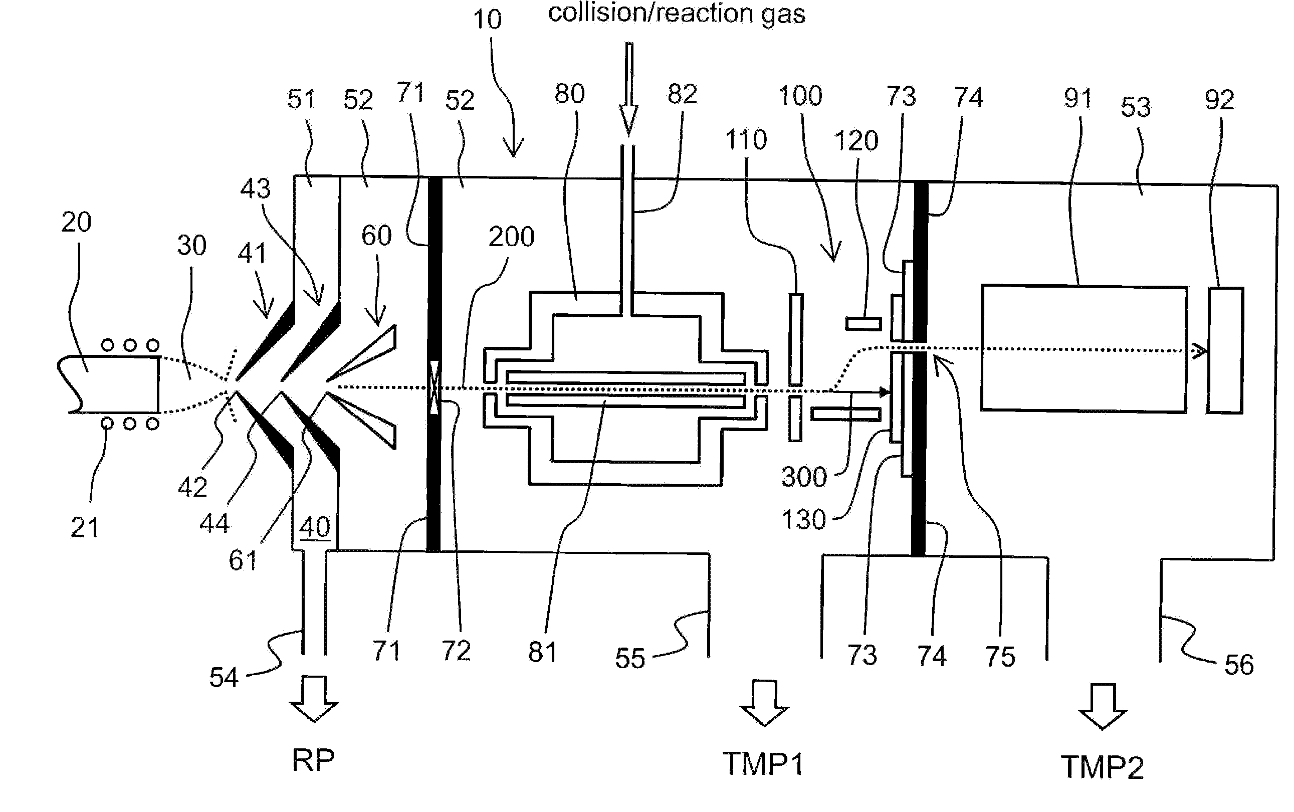
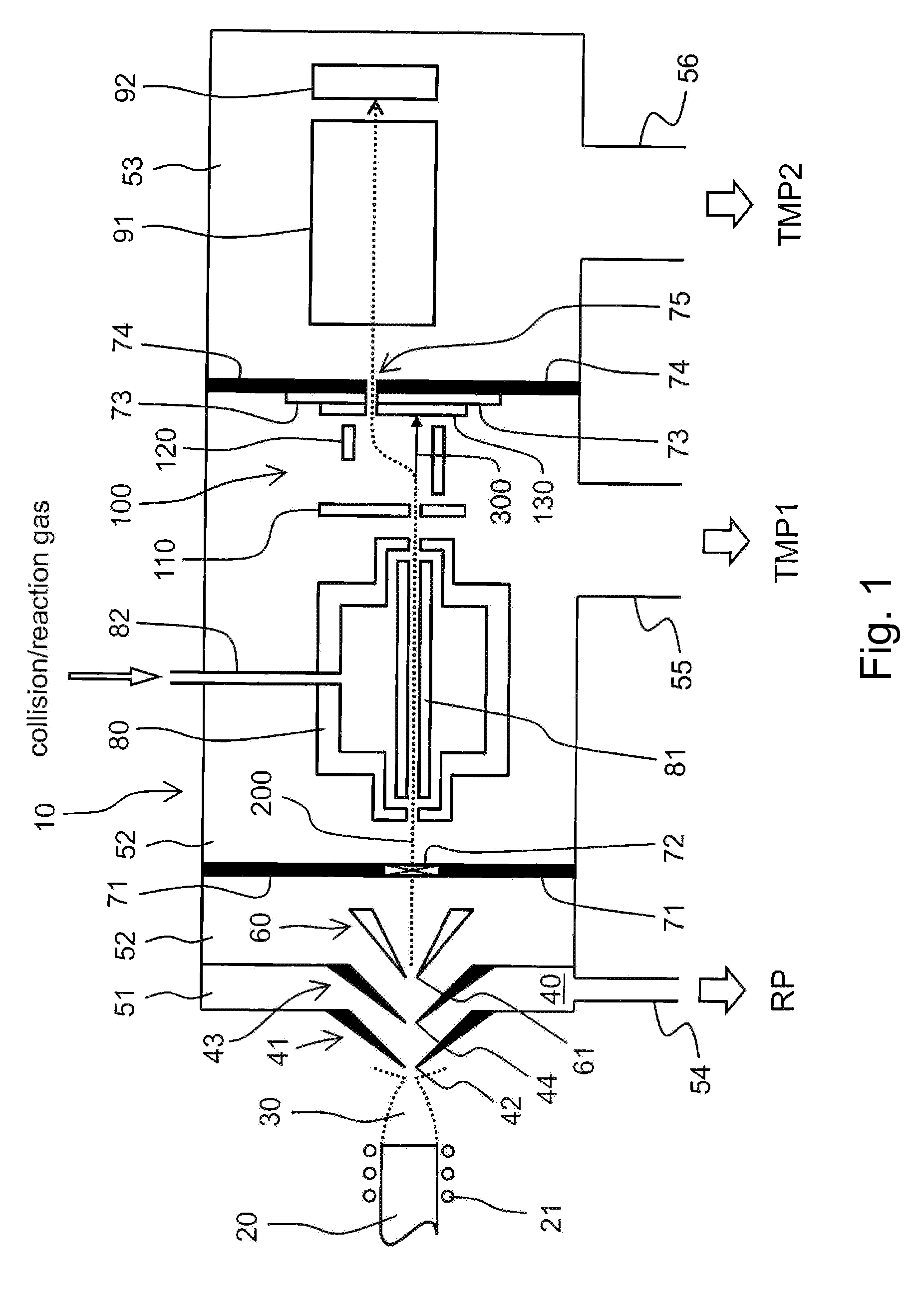
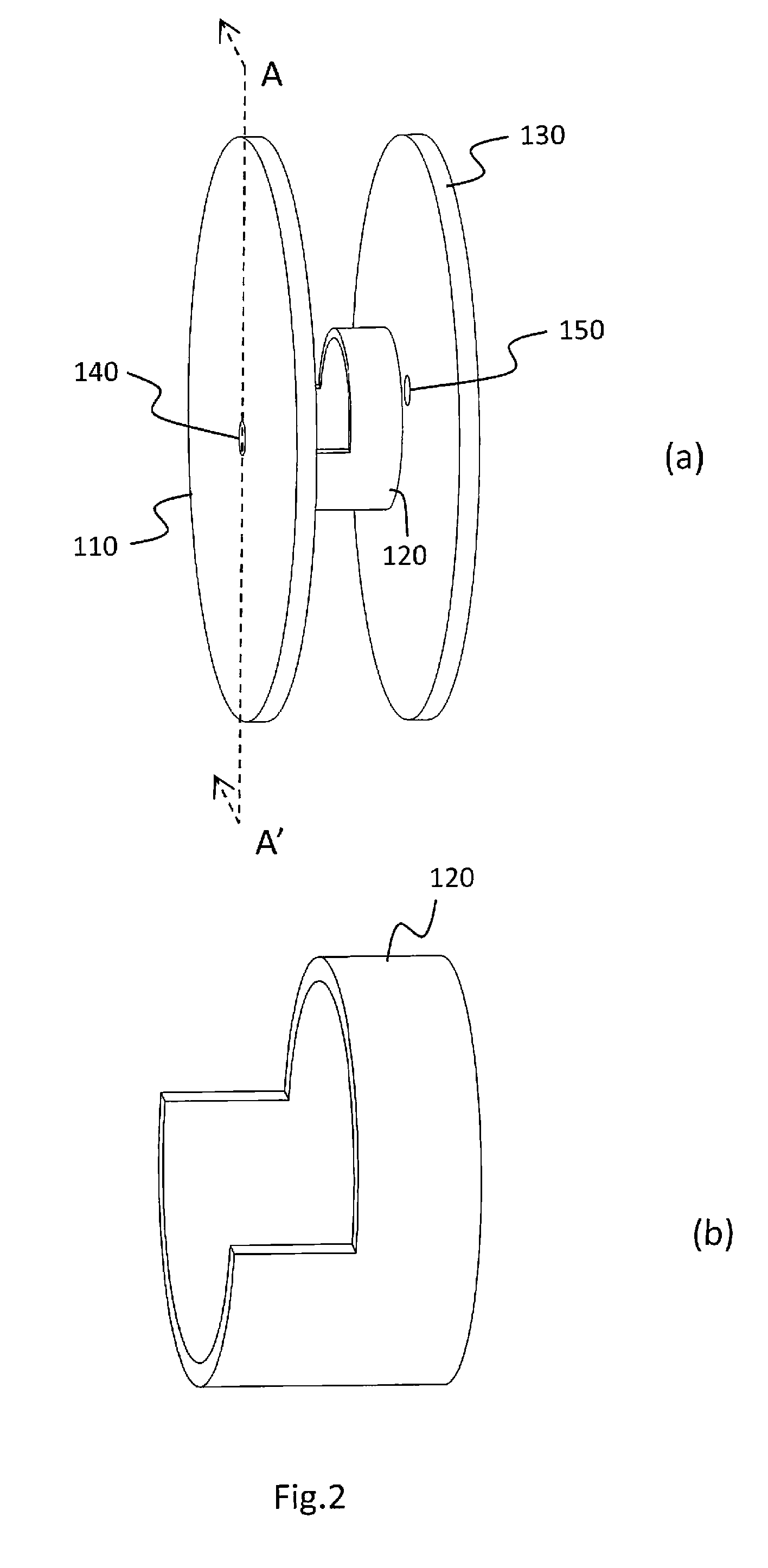
[0024]Hereinafter, a description is given of a preferred embodiment of the present invention with reference to the accompanying drawings. In this example, FIGS. 1 to 4 are referred to. FIG. 1 is a diagram illustrating a partial schematic configuration of an inductively coupled plasma mass spectrometer according to a first embodiment of the present invention. Hereinafter, the inductively coupled plasma mass spectrometer is simply referred to as “mass spectrometer”. Referring to FIG. 1, the configuration of the mass spectrometer 10 is illustrated in a cross-sectional view, but in actuality, the mass spectrometer 10 has a substantially tubular stereoscopic configuration which extends in the axial direction. FIGS. 2A and 2B are perspective views illustrating an ion deflector lens 100 which is a characteristic portion of the first embodiment. In FIGS. 2A and 2B, FIG. 2A is a view illustrating an entire ion deflector lens 100, and FIG. 2B is a view illustrating a part of the ion deflector...


PUM


Abstract

Provided is a plasma ion source mass spectrometer with an ion deflector lens having an improved removal ratio of photons and neutral particles as compared with the conventional art while an ion transmittance is maintained. The ion deflector includes an input side plate-like electrode, an output side plate-like electrode, and a tubular electrode disposed between the input side plate-like electrode and the output side plate-like electrode. The tubular electrode is of a point asymmetrical configuration. The tubular electrode is arranged so that a center axis of the tubular electrode is closer to an axis of travel of ions upstream of the input side plate-like electrode than an axis of travel of ions downstream of the output side plate-like electrode.

Description

BACKGROUND OF THE INVENTION[0001]1. Field of the Invention[0002]The present invention relates to a mass spectrometer using plasma as anion source, and more particularly, to amass spectrometer having an ion deflector lens.[0003]2. Description of the Related Art[0004]In a mass spectrometer using plasma as an ion source, such as an inductively coupled plasma mass spectrometer (ICP-MS) or a microwave plasma mass spectrometer (MIP-MS), it has been required that photons and neutral particles with high energy, which cause background noises, be separated from ion beams (for example, refer to JP 10-97838 A (FIG. 10), JP 2004-71470 A (FIG. 1), JP 8-7829 A (Paragraph [0009]), JP 2002-525821 A (FIG. 1), JP 61-107650 A (FIGS. 1 and 2), JP 2000-67805 A (FIG. 1), and JP 2000-100375 A (FIG. 2)).[0005]Conventionally, photons and neutral particles which cause the background noises are separated from ion beams by an aid of a tilted or bent ion guide (for example, refer to JP 10-97838 A). Hereinafter, ...

Claims


Application Information

Patent Timeline
IPC IPC(8): H01J49/00H01J3/14
CPCH01J37/14H01J49/0045H01J49/067H01J2237/14H01J2237/152H01J49/06
Inventor HIRANO, KAZUSHI
Owner AGILENT TECH INC
Why Eureka
Try Eureka