Electric-vehicle controller

a technology for electric vehicles and controllers, applied in the direction of electric devices, process and machine control, instruments, etc., can solve the problems of heat or electromagnetic force further destroying the electric-vehicle controllers and electric vehicles, and achieve the effect of preventing heat or electromagnetic for

Active Publication Date: 2009-10-29
NEXGEN CONTROL SYST LLC
View PDF20 Cites 17 Cited by
  • Summary
  • Abstract
  • Description
  • Claims
  • Application Information

AI Technical Summary

Benefits of technology

[0010]In an electric-vehicle controller according to the present invention, in the case where an abnormal circumstance has occurred or in the case where it is anticipated that an abnormal circums...

Problems solved by technology

Therefore, there has been a problem that, in the case where an external factor such as a collision exerts external force or impact on the electric-vehicle controller and the inner circuit of the electric-veh...

Method used


Image

  • Electric-vehicle controller
  • Electric-vehicle controller
  • Electric-vehicle controller

Examples


embodiment 1

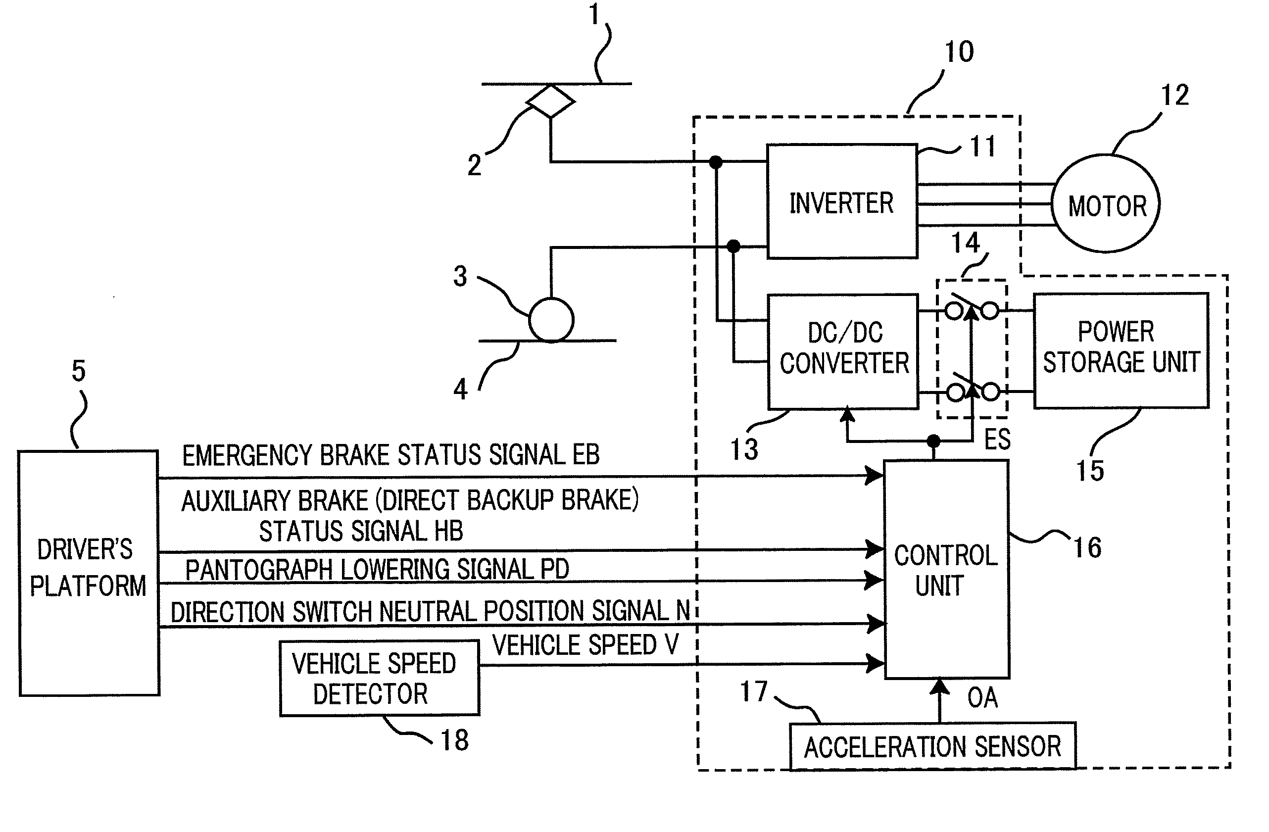
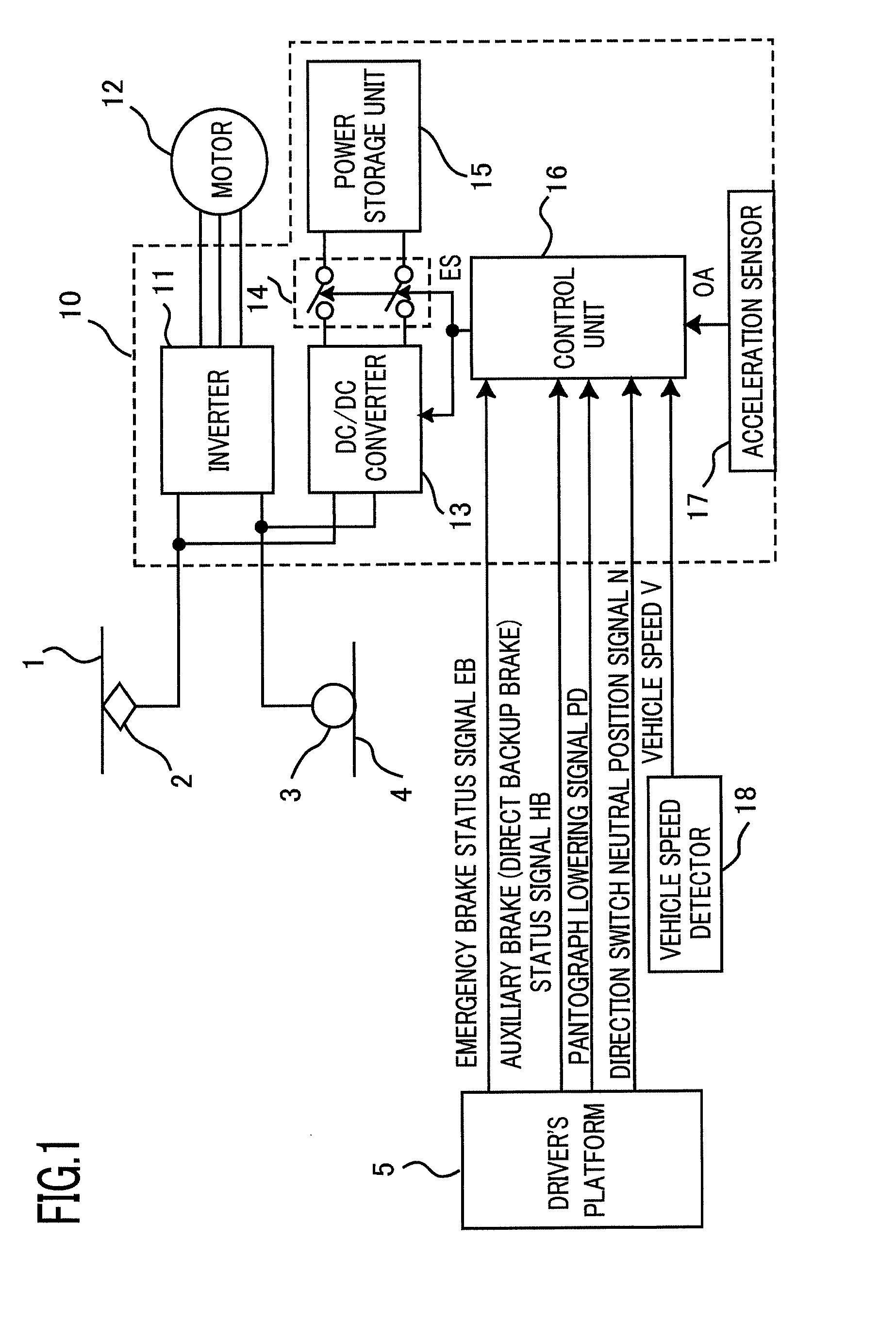
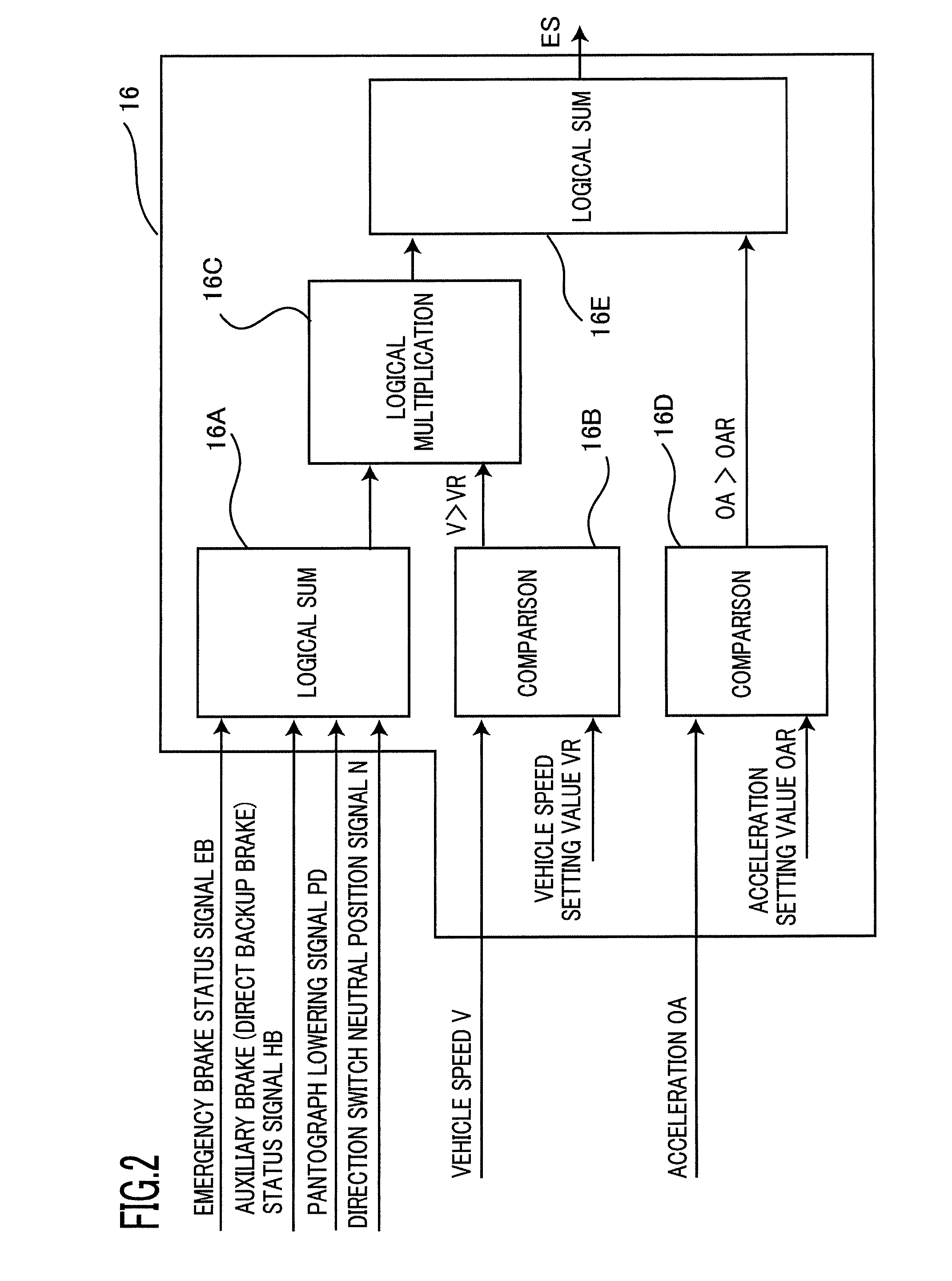
[0039]FIG. 1 is a block diagram illustrating an electric-vehicle controller according to Embodiment 1 of the present invention. As illustrated in FIG. 1, an electric-vehicle controller 10 is configured in such a way as to receive DC electric power from an overhead line 1 via a pantograph 2 and a wheel 3. The electric-vehicle controller 10 is configured with an inverter 11 that converts DC electric power (e.g., DC 1500 V) from the overhead line 1 into AC electric power (e.g., variable-voltage, variable-frequency electric power) and supplies the AC electric power to a motor 12; a power storage unit 15 that stores electric power for driving the inverter 11; a DC-to-DC converter 13, for making the power storage unit 15 store and discharge electric power, one terminal pair of which is connected to the DC power source side of the inverter 11 and the other terminal pair of which is connected to the power storage unit 15; a switch 14 connected between the power storage unit 15 and the DC-to...

embodiment 2

[0055]FIG. 3 is a block diagram illustrating an electric-vehicle controller according to Embodiment 2. Constituent elements that differ from those in the block diagram illustrated in FIG. 1 will be explained, and explanations for similar constituent elements will be omitted. In addition, the same reference characters in Figures denote the same or equivalent constituent elements. FIG. 3 illustrates an electric-vehicle controller utilized in an AC electrified section in which AC electric power is supplied to the overhead line 1. A converter 20 for converting the AC electric power in the overhead line 1 into DC electric power is connected to the DC side of the inverter 11. It goes without saying that the present invention is applicable also to such an electric-vehicle controller as configured in the foregoing manner.

[0056]The configuration according to Embodiment 2 can demonstrate an effect that, in the case where abnormal circumstances in which excessive impact is exerted on the elect...

embodiment 3

[0057]FIG. 4 is a block diagram illustrating an electric-vehicle controller according to Embodiment 3. Constituent elements that differ from those in the block diagram illustrated in FIG. 1 will be explained, and explanations for similar constituent elements will be omitted. FIG. 4 illustrates an electric-vehicle controller mounted in a vehicle that travels in a non-electrified section. AC electric power generated by an AC generator 30 that is driven by an internal combustion engine or the like is converted into DC electric power by the converter 20 and supplied to the inverter 11.

[0058]It goes without saying that the present invention is applicable also to such an electric-vehicle controller as configured in the foregoing manner. The configuration according to Embodiment 3 can demonstrate an effect that, in the case where abnormal circumstances in which excessive impact is exerted on the electric-vehicle controller 10 may occur or abnormal circumstances in which excessive impact is...


PUM


Abstract

There is obtained an electric-vehicle controller that prevents energy stored in a power storage unit from being discharged in the case where a collision, a derailment, or breakage of an overhead line occurs. The electric-vehicle controller is provided with a DC-to-DC converter one terminal pair of which is connected to the DC power source side of the inverter, a power storage unit that is connected to the other terminal pair of the DC-to-DC converter and stores electric power, a switch provided between the power storage unit and the DC-to-DC converter, and a control unit that opens the switch in the case where abnormal circumstances may occur or have occurred.

Description

TECHNICAL FIELD[0001]The present invention relates to an electric-vehicle controller equipped with a power storage unit in which DC power is charged and from which DC power is discharged.BACKGROUND ART[0002]To date, it has been known that the kinetic energy of the vehicle can effectively be utilized, by mounting in an electric vehicle an electric-controller in which a power storage unit is integrated with an inverter that drives a motor of the electric vehicle, storing in the power storage unit superfluous regenerative electric power produced when the vehicle is braked, and utilizing the stored power when the vehicle is accelerated or when an overhead line voltage is lowered (e.g., Patent Document 1). In addition, the power storage unit is formed of a power storage device such as a secondary battery, an electric double-layer capacitor, or the like.[0003]In order to obtain electric power that is large enough to drive an electric vehicle, the electric power accumulated in the power st...

Claims


Application Information

Patent Timeline
IPC IPC(8): H02H7/18B60L50/15
CPCB60L3/0007B60L2200/26B60L9/22B60L11/123B60L11/1801B60L11/1803B60L2210/10B60L2210/40B60L2240/12B60L2240/14Y02T10/6217Y02T10/7005Y02T10/7077Y02T10/7216Y02T10/7241B60L3/04B60L50/51B60L50/53B60L50/61Y02T10/62Y02T10/70Y02T10/72B60L9/18Y02T10/7072
Inventor KITANAKA, HIDETOSHI
Owner NEXGEN CONTROL SYST LLC
Why Eureka
Try Eureka