High dynamic range sensor system and method

Active Publication Date: 2009-10-29
ROCKWELL COLLINS INC
View PDF18 Cites 183 Cited by
  • Summary
  • Abstract
  • Description
  • Claims
  • Application Information

AI Technical Summary

Benefits of technology

[0014]Although the present invention is especially beneficial for electronic night vision, the principles herein can dramatically improve the performance of numerous wide dynamic range optical imaging systems. For example, the principles herein can be extend

Problems solved by technology

A significant disadvantage of the concept presented by Nakamura and Saitoh is the requirement for multiple sequential scans of a scene, which results in image degradation and limits the potential dynamic range extension.
A further disadvantage of the de

Method used


Image

  • High dynamic range sensor system and method
  • High dynamic range sensor system and method
  • High dynamic range sensor system and method

Examples


Example

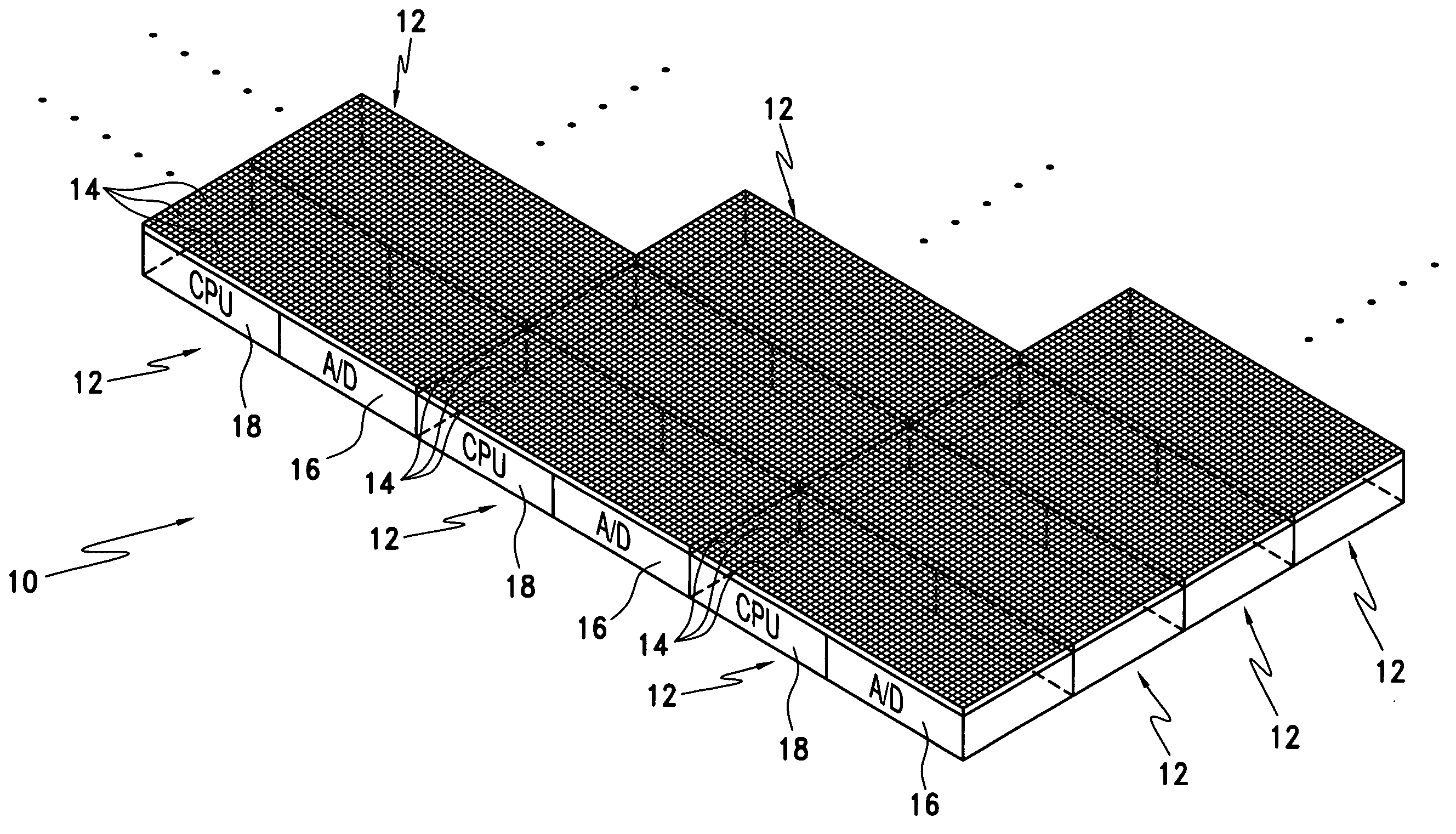
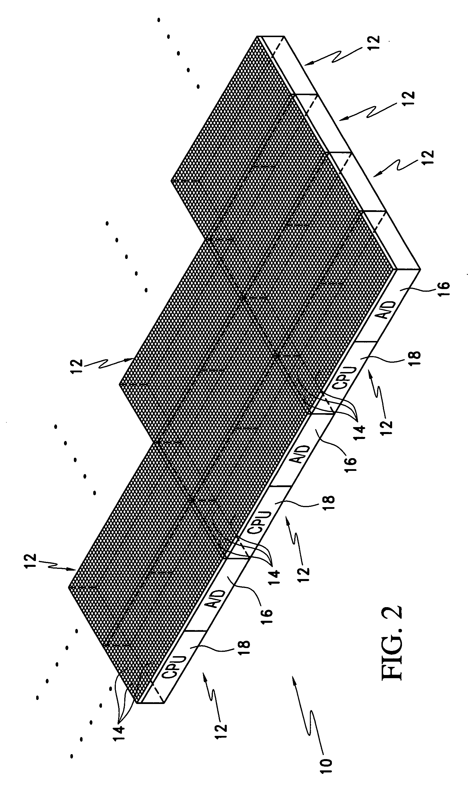
[0024]Referring now to FIG. 2, a schematic representation of a high dynamic range sensor assembly of the present invention is illustrated, designated generally as 10. The high dynamic range sensor assembly 10 comprises multiple pixel sets (i.e. “sensing sets” or “clusters”), each designated generally as 12 that are organized into a sensing array. Each pixel set includes a set of sensing elements 14 for sensing physical phenomena. The set of sensing elements 14 have a locally selectable integration time. An analog-to-digital (A / D) converter 16 is operatively connected to the set of sensing elements 14 for acquisition and conversion of an analog signal of each of the sensing elements 14 into a digital signal. A processor 18 is operatively connected to the A / D converter 16 and to the set of sensing elements 14 for managing the selectable integration time for the set of sensing elements 14 and for analyzing the digital signals from each of the sensing elements 14 in the set of sensing e...


PUM


Abstract

A high dynamic range sensor assembly includes a plurality of sensing sets that are organized into a sensing array. Each of the sensing sets includes a set of sensing elements for sensing physical phenomena. Each set of sensing elements has a locally selectable integration time. An analog-to-digital (A/D) converter operatively connected to the set of sensing elements acquires and converts an analog signal from each of the sensing elements into a digital signal. A processor operatively connected to the A/D converter and to the set of sensing elements manages the selectable integration time for the set of sensing elements and analyzes the digital signals from each of the sensing elements in the set of sensing elements. The digital signals from each of the sensing elements are measured by the processor and an integration scaling factor for the set of sensing elements is computed and controlled by the processor to adjust the integration time. The integration scaling factor for the set of sensing elements is mathematically combined with a value of the digital signal from the A/D converter to form a larger data word than what is generated by the A/D converter. The larger data word is utilized to represent a magnitude of each of the sensing elements. If a substantial number of A/D values have saturated, the integration time is decreased; and, if a substantial number of A/D values are below a predetermined threshold, the integration time is increased.

Description

BACKGROUND OF THE INVENTION[0001]1. Field of the Invention[0002]The present invention relates generally to sensing of physical phenomena, particularly to optical image sensing, and more particularly to high dynamic range optical imaging for digital electronic night vision.[0003]2. Description of the Related Art[0004]Night vision capability provides warfighters a significant force multiplication benefit. Military operations are increasingly being conducted in urban terrain, which is much more demanding of dynamic range than traditional rural venues. In particular, soldiers conducting military operations during night in urban terrain may encounter light conditions ranging from “overcast starlight” to relatively bright artificial lighting. The dynamic range within a single scene may vary by 6 or 7 orders of magnitude or more, ranging from street lights (approximately 10 lux) to dark alleys (approximately 1 microlux). Present night vision systems use a single user adjustable exposure co...

Claims


Application Information

Patent Timeline
IPC IPC(8): G01C3/02
CPCG01C3/06
Inventor KOENCK, STEVEN E.JENSEN, DAVID W.
Owner ROCKWELL COLLINS INC
Why Eureka
Try Eureka