Cycle slip detection for timing recovery

a timing recovery and cycle slip technology, applied in the direction of noise figure or signal-to-noise ratio measurement, digital transmission, instruments, etc., can solve the problems of low signal-to-noise ratio, more challenging timing recovery, and burst errors, so as to improve cycle slip detection and low signal-to-noise ratio

Inactive Publication Date: 2009-10-29
MAGNOLIA LICENSING LLC
View PDF3 Cites 24 Cited by
  • Summary
  • Abstract
  • Description
  • Claims
  • Application Information

AI Technical Summary

Benefits of technology

[0005]It is an aspect of the invention to improve cycle slip detection for a fully digital implementation of a timing

Problems solved by technology

With increased density, magnetic and optical storage systems exhibit high intersymbol interference and low signal to noise ratios, which makes timing recovery more challenging.
Due to loss of bit synchronization, cycle slips result in burst errors.
However, zero-crossing based timing recovery is expected to perform poor under intersymbol interference and low signal to noise ratio conditions, because zero-crossings of the read-out signal do not provide reliable timing information under such conditions.
Moreover, two adj

Method used


Image

  • Cycle slip detection for timing recovery
  • Cycle slip detection for timing recovery
  • Cycle slip detection for timing recovery

Examples


Embodiment Construction

[0030]Like numerals and characters designate like elements throughout the figures of the drawings.

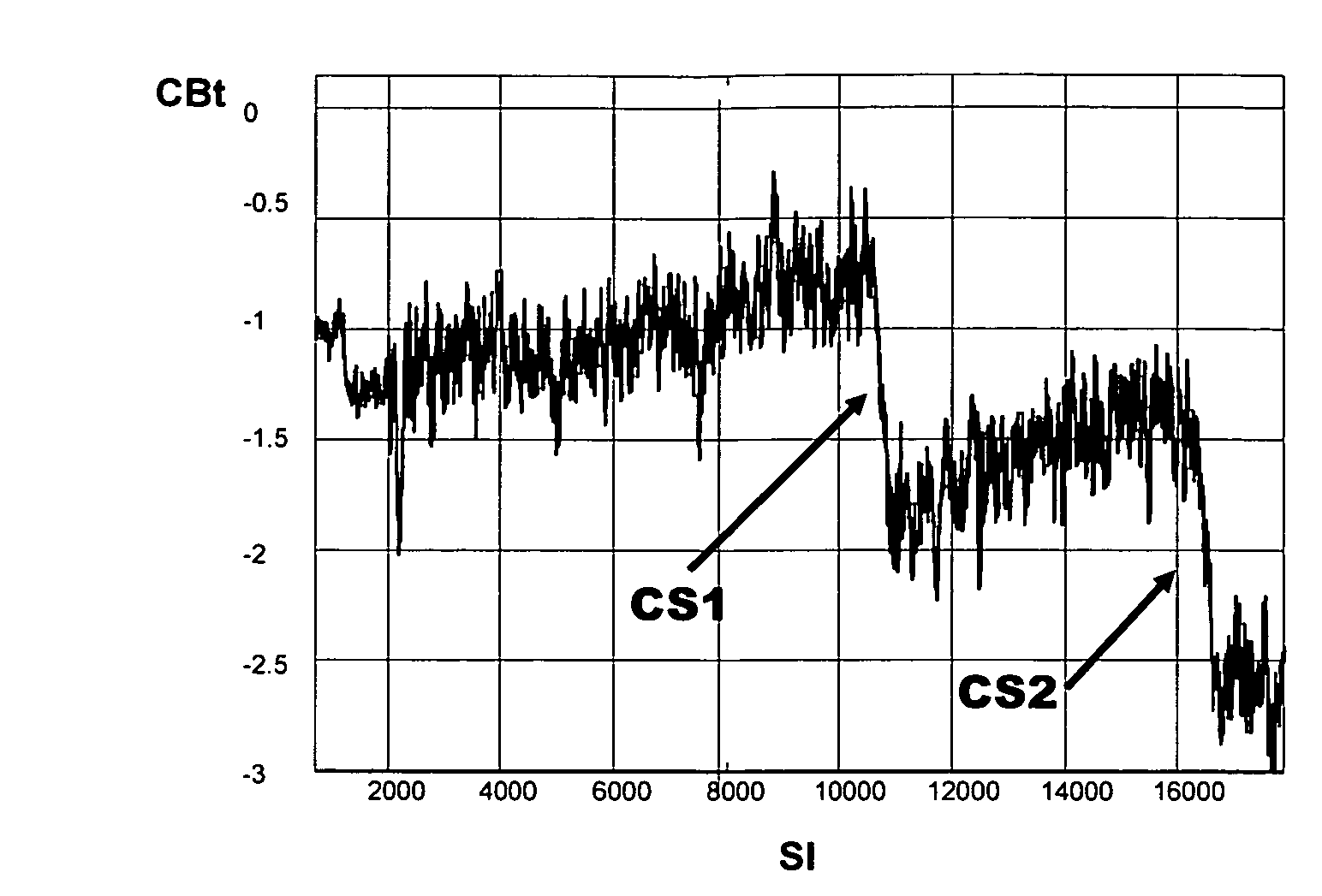
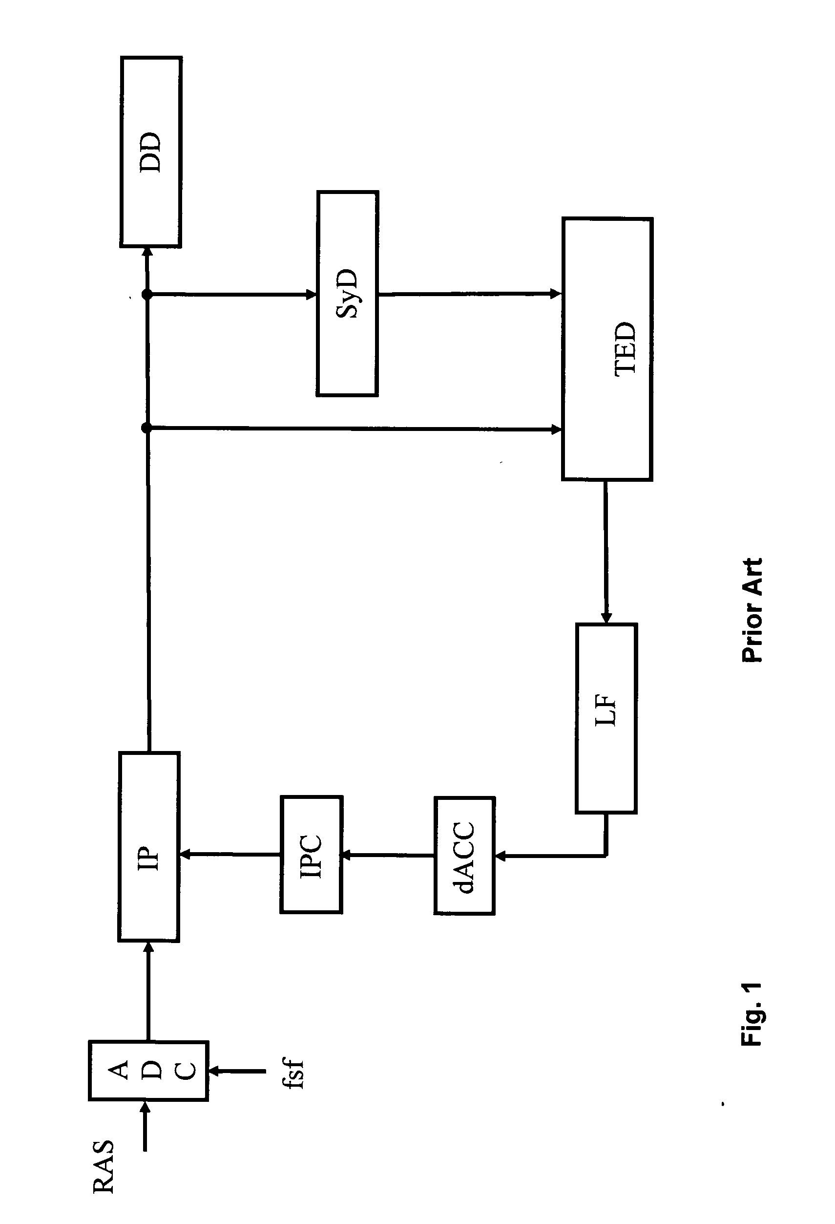
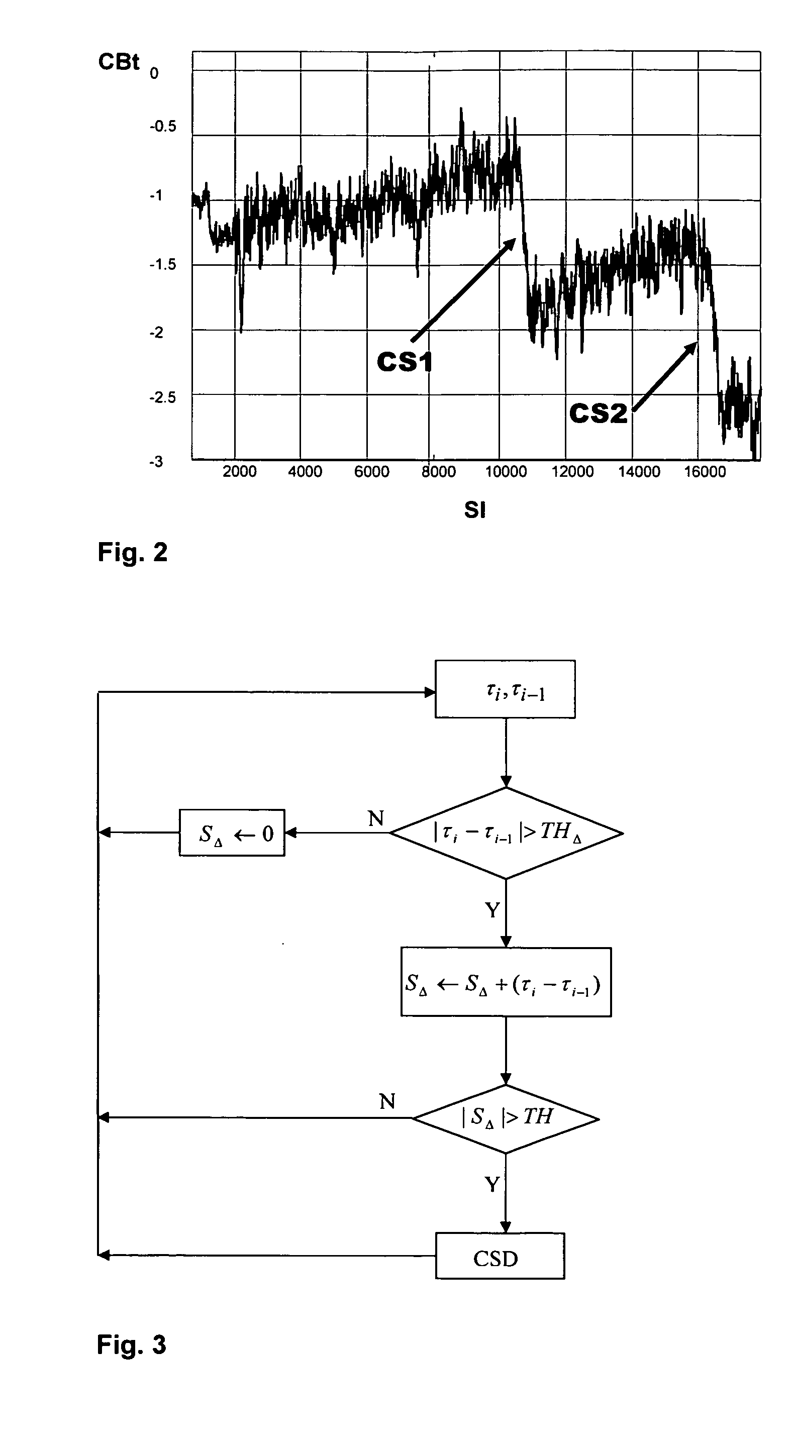
[0031]Reference is initially directed to FIG. 1, which generally illustrates the basic portions of a fully digital implementation of a timing recovery control loop for interpolated timing recovery as disclosed in FIG. 27.2 by P. Kovintavewat et al, “Interpolated timing recovery”, in CRC Handbook of Coding and Signal Processing for Magnetic Recording Systems, 2005, pp. 27-1-27-16. A received analog signal RAS comprising digital data as e.g. provided by reading a high-density data storage medium or received by mobile phone is applied to an analog digital converter ADC having a fixed sampling frequency fsf, which means that the received signal is asynchronously sampled. The advantage of asynchronous sampling is that the sampling frequency does not need to be a multiple of the symbol frequency and a system known as interpolated timing recovery is employed for timing adjustment to obtain syn...


PUM


Abstract

A method and an arrangement for cycle slip detection for timing recovery of a received analog signal comprising asynchronously sampled digital data are recommended. More specifically a fully digital implementation of a timing recovery control loop using a technique known as interpolated timing recovery and improved cycle slip detection as well as improved cycle slip correction based on said cycle slip detection are recommended. The method comprises the steps of using an output signal of the loop filter in the control loop for timing recovery, generating averaged timing error values from said filtered timing error signal and accumulating changes of the averaged timing error values in adjacent blocks of samples which exceed a first threshold. Accumulated averaged timing error changes of adjacent blocks which exceed a second threshold are then declared as cycle slip and the number of cycle slips is determined by a third threshold being a tolerance threshold. Furthermore, a first-in, first-out memory is provided for sample insertion or deletion, which means that a sample insertion or sample deletion takes place in the sample domain with increased reliability and an improved method for cycle slip detection is recommended due to increased robustness against noise and inappropriately chosen timing loop parameters, which is also applicability for systems with frequency-offsets. The method and a corresponding arrangement are applicable for timing recovery of signals having high intersymbol interference, low signal to noise ratio and frequency offset as e.g. provided by reading a high-density data storage medium or received by mobile phone.

Description

FIELD OF THE INVENTION[0001]The present invention relates to a method and an arrangement for cycle slip detection for timing recovery, more specifically a fully digital implementation of a timing recovery control loop using a technique known as interpolated timing recovery and improved cycle slip detection as well as improved cycle slip correction based on said cycle slip detection.BACKGROUND OF THE INVENTION[0002]It is the purpose of timing recovery to convert an asynchronously sampled read-out signal to a baud rate synchronous signal, which e.g. is used for bit detection, runlength limited decoding or joint bit detection and runlength limited decoding or subsequent channel decoding. A fully digital implementation of timing recovery control loop using a technique known as interpolated timing recovery abbreviated as ITR already has been disclosed by P. Kovintavewat et al, “Interpolated timing recovery”, in CRC Handbook of Coding and Signal Processing for Magnetic Recording Systems, ...

Claims


Application Information

Patent Timeline
IPC IPC(8): H04L7/00
CPCH03L2207/50H04L7/0029H04L7/005H04L7/0083H04L7/0062H04L7/00
Inventor CHEN, XIAO-MINGTHEIS, OLIVER
Owner MAGNOLIA LICENSING LLC
Why Eureka
Try Eureka