Ice shed reduction for leading edge structures

Active Publication Date: 2009-11-05
GENERAL ELECTRIC CO
View PDF23 Cites 10 Cited by
  • Summary
  • Abstract
  • Description
  • Claims
  • Application Information

AI Technical Summary

Benefits of technology

[0008]These and other shortcomings of the prior art are addressed by the present invention, which provides components having icephobic plating that reduces and / or modifies ice adhesion forces to promote ice release and reduce shedding of large ice pieces.

Problems solved by technology

The downside of titanium is the expense and weight when compared to conventionally treated aluminum.
However, conventionally treated aluminum is believed to behave poorly in an aircraft icing environment.
While these coatings can improve ice shedding characteristics, their erosion resistance may be not adequate to protect leading edge structures from the scrubbing effect of airflows with entrained abrasive particles which are encountered in flight.

Method used


Image

  • Ice shed reduction for leading edge structures
  • Ice shed reduction for leading edge structures
  • Ice shed reduction for leading edge structures

Examples


Embodiment Construction

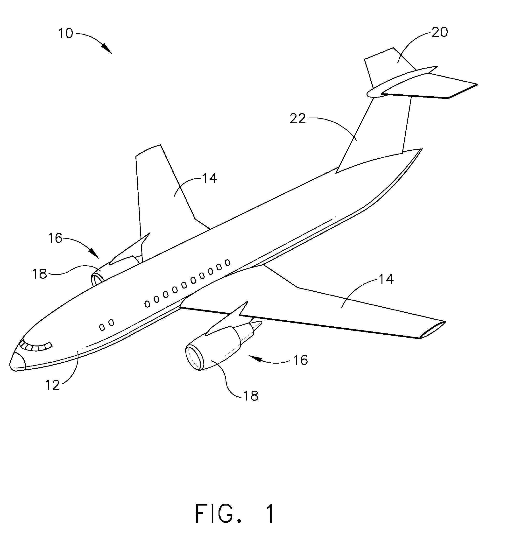
[0028]Referring to the drawings wherein identical reference numerals denote the same elements throughout the various views, FIG. 1 depicts a known type of commercial aircraft 10 which includes a generally tubular fuselage 12, wings 14 carrying turbofan engines 16 mounted in nacelles 18, and an empennage comprising horizontal and vertical stabilizers 20 and 22. Each of these components includes one or more exposed surfaces having a curved or airfoil-like cross-section that faces the direction of flight (in other words an aerodynamic leading edge). These surfaces are referred to herein as “leading edge structures”. While the present invention will be described further in the context of a gas turbine engine, it will be understood that the principles contained therein may be applied to any type of leading edge structure.

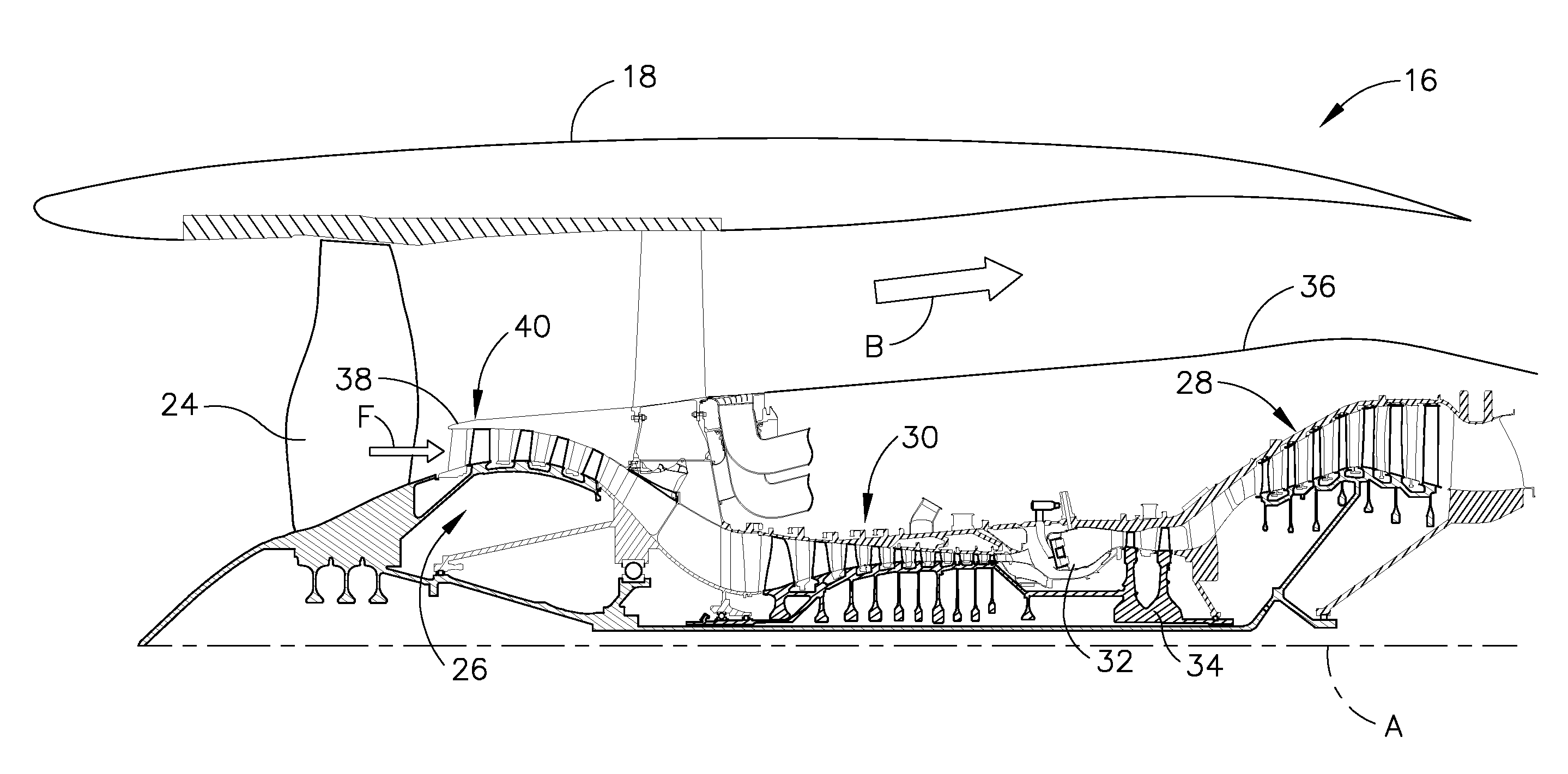
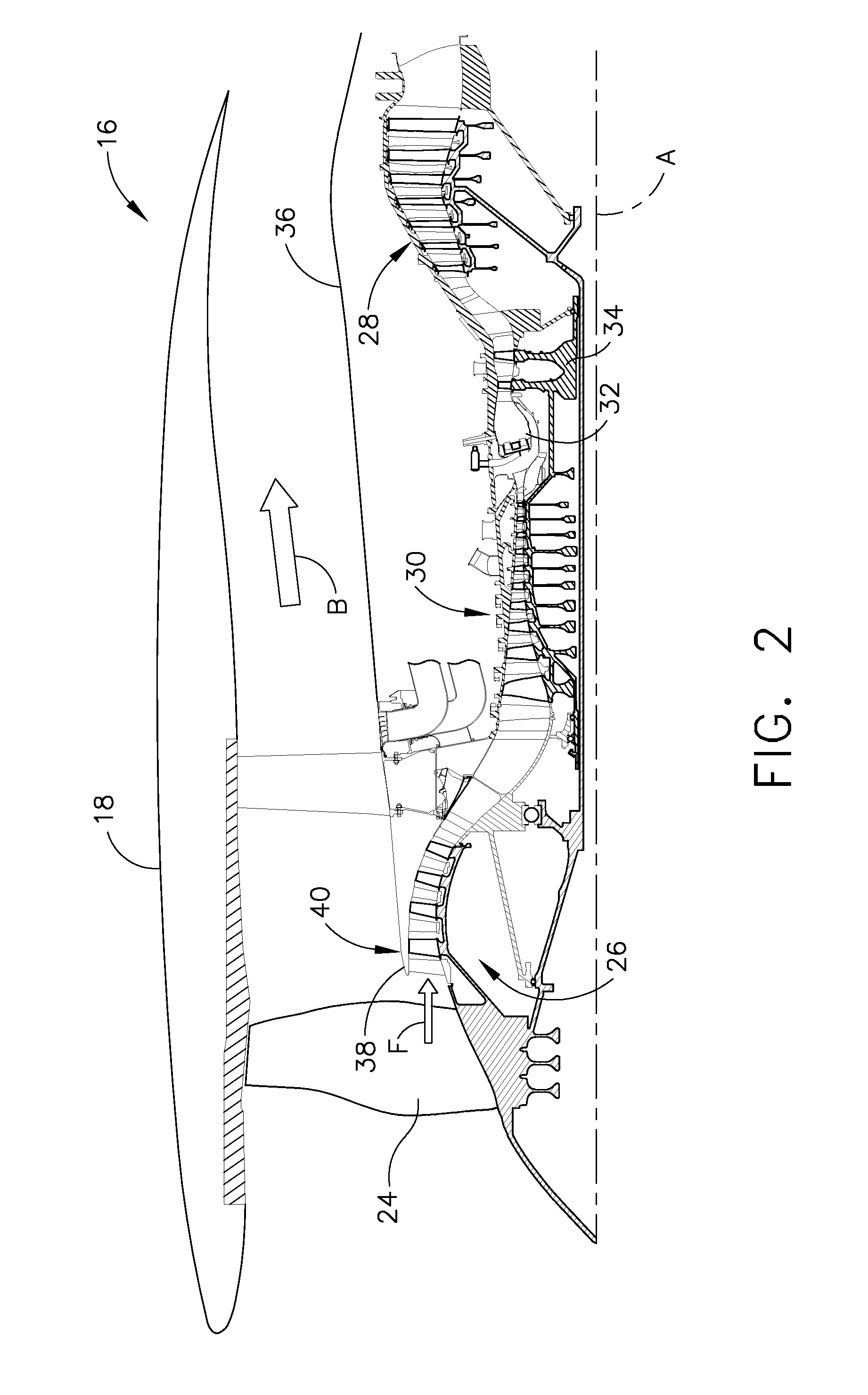
[0029]As shown in FIG. 2, the engine 16 has a longitudinal axis “A” and includes conventional components including a fan 24, a low pressure compressor or “booster”26 and...


PUM


Abstract

A leading edge structure for use in an aerospace vehicle includes a body having a flowpath surface which defines a leading edge adapted to face an air flow during operation, and an opposed inner surface. The body is segmented into a plurality of portions having varying thermal properties and / or mechanical discontinuities, so as to promote stress concentrations in ice attached to the flowpath surface.

Description

BACKGROUND OF THE INVENTION[0001]This invention relates generally to aerospace vehicle structures and more particularly to designs for improving ice shedding characteristics from such structures.[0002]All aircraft include various “leading edge structures”, i.e. exposed surfaces that face the direction of flight. These surfaces include, for example, parts of the fuselage, wings, control surfaces, and powerplants.[0003]One common type of aircraft powerplant is a turbofan engine, which includes a turbomachinery core having a high pressure compressor, combustor, and high pressure turbine in serial flow relationship. The core is operable in a known manner to generate a flow of propulsive gas. A low pressure turbine driven by the core exhaust gases drives a fan through a shaft to generate a propulsive bypass flow. The low pressure turbine also drives a low pressure compressor or “booster” which supercharges the inlet flow to the high pressure compressor.[0004]Certain flight conditions all...

Claims


Application Information

Patent Timeline
IPC IPC(8): B64D15/18F02G3/00
CPCB64D15/00B64D33/02B64D2033/0233B64D2033/0286F05D2300/50212F01D25/02F01D25/162F02C7/047F01D9/04B64C3/28B64C5/00B64C7/00B64D15/16
Inventor RAINOUS, EDWARD ATWOODALLMON, BARRY LYNNLOEWE, JEFFRE GERRYBROOKS, WILLIAM CLARKEBLANTON, LEE ALANTUDOR, COURTNEY JAMESBUDINGER, VICKY SHOWALTER
Owner GENERAL ELECTRIC CO
Why Eureka
Try Eureka