
Display particles for image display device and image display device installed with the same

Inactive Publication Date: 2010-12-02
KONICA MINOLTA BUSINESS TECH INC
View PDF4 Cites 1 Cited by
  • Summary
  • Abstract
  • Description
  • Claims
  • Application Information

AI Technical Summary

Benefits of technology

[0009]According to the present invention, the inorganic fine particles (external additive) added externally in display particles are effective not only in reducing adhesive force of the display particles to display particle-contacting surfaces of substrates, but also in expressing bearing effect of relaxing collisional force among the display particles. Thus, relative high-contrast images can be displayed repeatedly even when the operating voltage is relatively lower.

Problems solved by technology

However, it was not possible to reduce operating voltage sufficiently and thus, there existed requirements for further reduction of the operating voltage.

Method used


Image

  • Display particles for image display device and image display device installed with the same
  • Display particles for image display device and image display device installed with the same
  • Display particles for image display device and image display device installed with the same

Examples


example 1

[0107]Preparation of White Display Particles

[0108]White Base Particle

[0109]The resin and titanium oxide described below were placed in a Henschel mixer (manufactured by Mitsui Miike Machinery Co., Ltd.) and mixed therein with an agitating-blade peripheral speed adjusted to 25 m / sec for 5 minutes, to give a mixture.

Styrene acrylic resin (weight-average100 parts by weightmolecular weight: 20,000)Anatase titanium oxide (average primary 30 parts by weightparticle size: 150 nm)

[0110]The mixture of the above was placed and kneaded in a biaxial extrusion kneader, pulverized coarsely in a hammer mill, then pulverized finely in a turbo mill pulvelizer (manufactured by Turbo Kogyo) and further classified in an air classifier utilizing Coanda effect, to give white base particles having a volume-average diameter of 10.0 μm.

[0111]Pretreatment

[0112]Five parts by weight of silica particles (hydrophobicity: 75%) having an average primary particle size of 100 nm treated with an aminosilane-based cou...

example 2

[0136]An image display device was prepared in a manner similar to Example 1, except that the white and black display particles prepared by the following methods were used.

[0137]Preparation of White Display Particles

[0138]Mild-Condition Mixing-Treatment

[0139]One hundred parts by weight of the white base particles similar to those in Example 1, 0.4 part by weight of silica particles (hydrophobicity: 78%) having an average primary particle size of 15 nm treated with an aminosilane-based coupling agent (aminopropyltrimethoxysilane) and 300 parts by weight of glass beads having an average primary particle size of 1 mm were placed in a 500-cc pot, and mixed with a Turbula mixer (manufactured by Glen Mills Inc.) at 100 rpm for 5 minutes. The mixture obtained was filtered through a mesh sieve for removal of the glass beads to give white display particles. The content of the primary particles having a primary particle size of 5 to 60 nm in the silica particles was 80 wt %.

[0140]Preparation o...


PUM

PropertyMeasurementUnit
Currentaaaaaaaaaa
Currentaaaaaaaaaa
Nanoscale particle sizeaaaaaaaaaa

Abstract

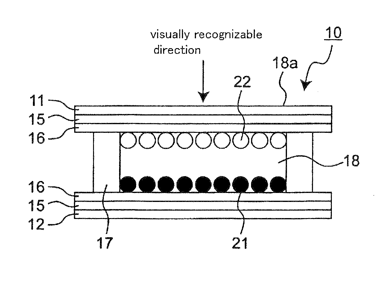
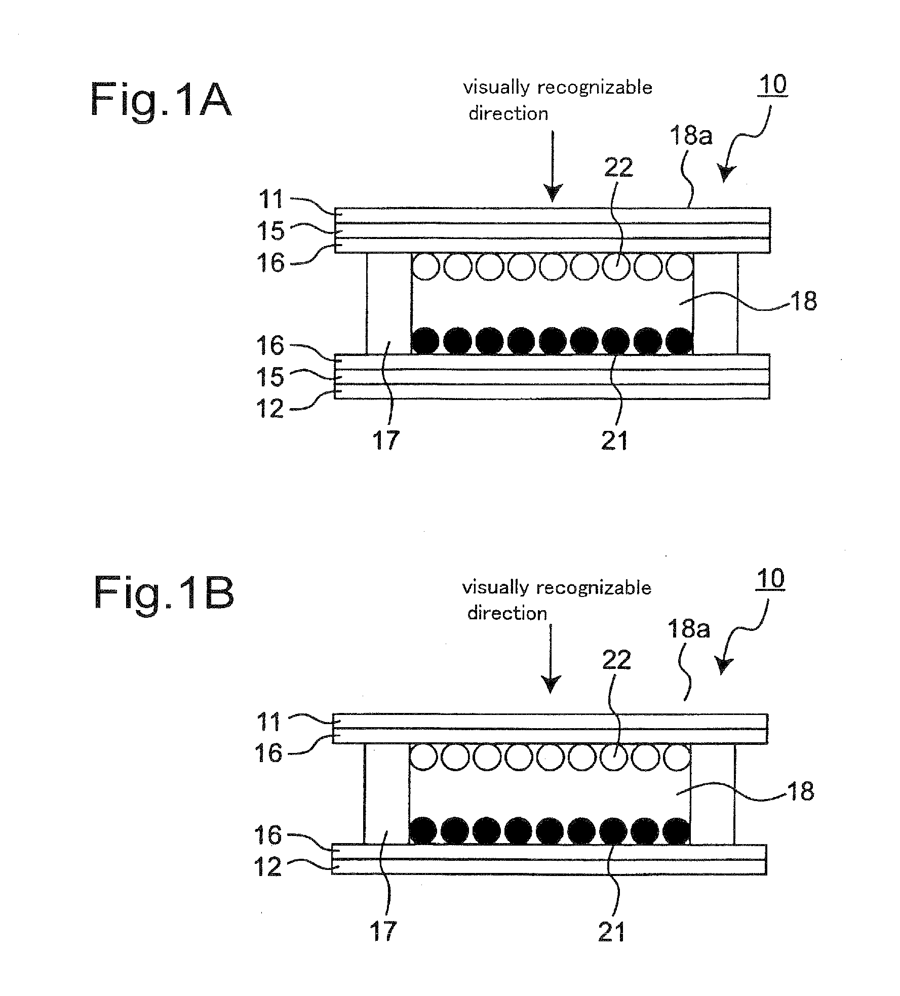
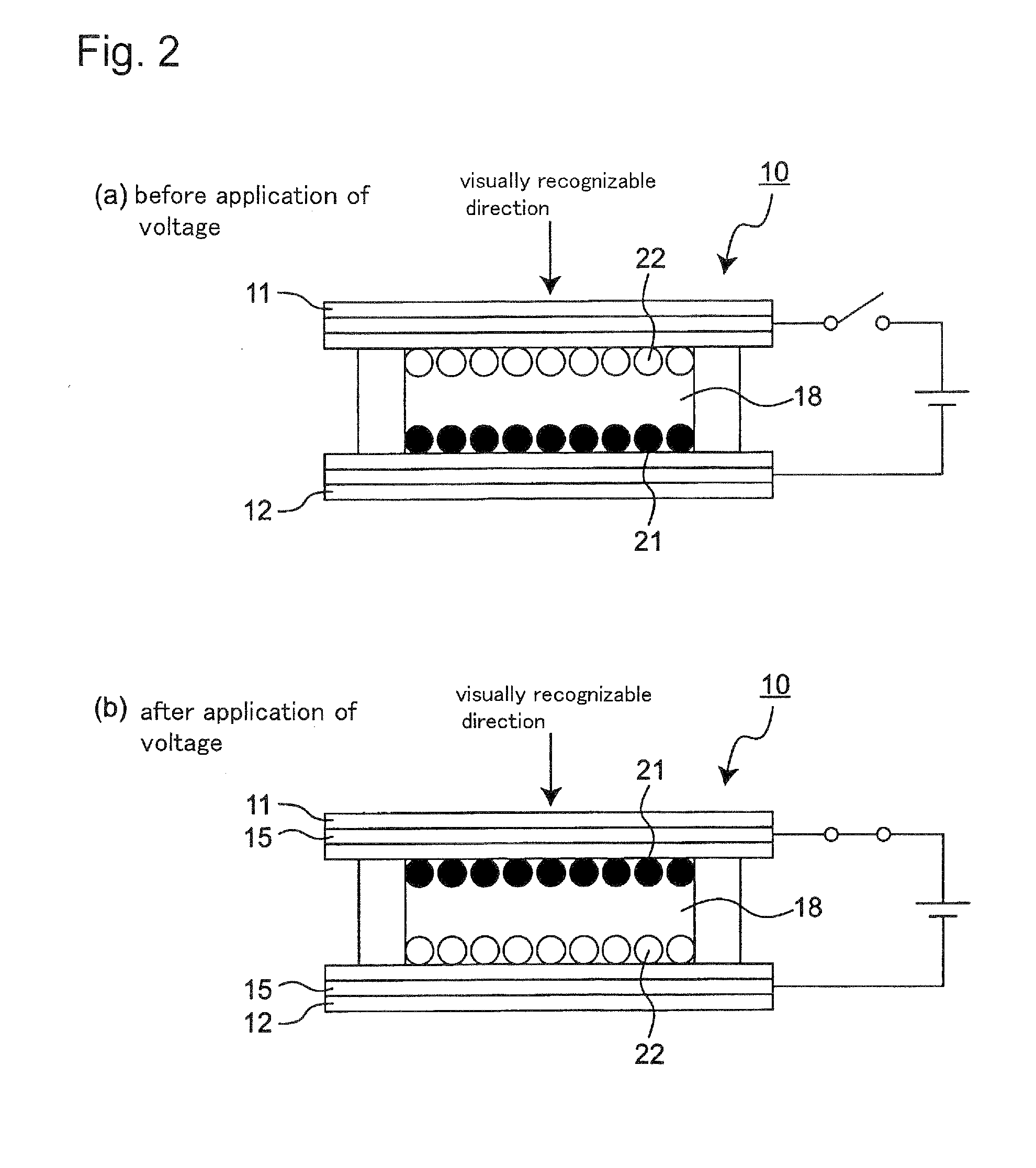
Display particles for use in image display devices with display particles sealed in a powdery form in the space between two substrates, at least one of which is transparent, that display an image while the display particles are moved as electric field is generated between the substrates, characterized in that the display particles contain at least base particles containing at least a resin and a colorant and inorganic fine particles added to the base particle; externally and a separation amount A of the inorganic fine particles having a primary particle size of 5 to 60 nm separated from the display particles when the particles are provided with an ultrasonic energy of 60 μA for 1 minute in aqueous polyoxyethylphenylether solution is 0.1 to 2.5 wt % with respect to the base particles, and an image display device installed with the display particles for image display devices.

Description

TECHNICAL FIELD[0001]The present invention relates to an image display device displaying and erasing images repeatedly by movement of display particles in applied electric field and display particles for use in the image display device.BACKGROUND ART[0002]Image display devices displaying images by movement of display particles in the gas phase have been known. Such an image display device contains powdery display particles sealed in the area between two substrates, at least one of which is transparent, and an image is displayed by movement and adhesion of the display particle onto one substrate in electric field generated between the substrates. It is possible by operation of such an image display device to display and erase images repeatedly by properly selecting the direction of the electric field, because the display particles move along with the direction of the electric field, which is formed by application of a voltage between the substrates. For that reason, there existed req...

Claims


Application Information

Patent Timeline
IPC IPC(8): G02F1/167B32B1/00G02F1/1671
CPCG02F1/167G02F1/1671Y10T428/2991G02F2001/1678
Inventor HOSOYA, YUKIOOKUYAMA, OKUSHIUCHINO, SATOSHIKONNO, HIROYUKINAGASE, TATSUYA
Owner KONICA MINOLTA BUSINESS TECH INC
Learn More