Electroluminescent displays

Active Publication Date: 2009-11-05
MFLEX UK
View PDF8 Cites 3 Cited by
  • Summary
  • Abstract
  • Description
  • Claims
  • Application Information

AI Technical Summary

Benefits of technology

[0008]A layer according to the invention is advantageous as when incorporated in a light, such as a backlight for a display, an electric field can be applied across the electroluminescent layer to cause the phosphor to emit light, and in conditions where there is high intensity light incident on the light, the fluorescent pigment or dye of the layer colours light reflected from the phosphor particles / backlight to maintain the desired colour contrast of the light. Therefore, a pale, washed out look to the light is avoided, while the number of print passes to manufacture the light are reduced compared to those lights having a filter layer.
[0022]The display is advantageous as no filter layer is required that could adversely affect the electric field across the electroluminescent layer. Eliminating the need for a filter layer reduces the manufacturing costs of the display because fewer printed layers are required.
[0025]Using such a material, the combination of a liquid crystal shutter in front of an electroluminescent display results in a hybrid display that not only emits light when activated but also changes reflectivity when activated. This type of hybrid display can have good visibility in a very large range of lighting conditions—from pitch darkness to full sunlight (typically considered the highest ambient light conditions).
[0026]There is another significant advantage related to nematic materials: selection of a liquid crystal material which absorbs light in the absence of an electric field and transmits light when an electric field is present allows the same electric field to be used to drive the electroluminescent material as is used to drive the liquid crystal material. In the absence of an electric field, the liquid crystal material absorbs incident ambient light and the electroluminescent material does not generate any light so the display element appears dark. When an electric field is applied, the liquid crystal transmits both incident ambient light, which subsequently reflects back out off the electroluminescent layer behind it, and also the light now generated by the electroluminescent layer, so the display appears light.

Problems solved by technology

It has been found that in conditions where there is high intensity light incident on the display, such as in bright daylight, the weakly emissive EL backlight is difficult to make out as the light emitted by the EL backlight is overwhelmed by the brighter incident light reflected from the EL backlight.
However, the filter layer affects the electric field across the EL and PDLC layers, adversely affecting performance, and the display is expensive to manufacture, requiring an additional print pass for each colour filter layer (typically one for each phosphor colour).

Method used


Image

  • Electroluminescent displays
  • Electroluminescent displays

Examples


Embodiment Construction

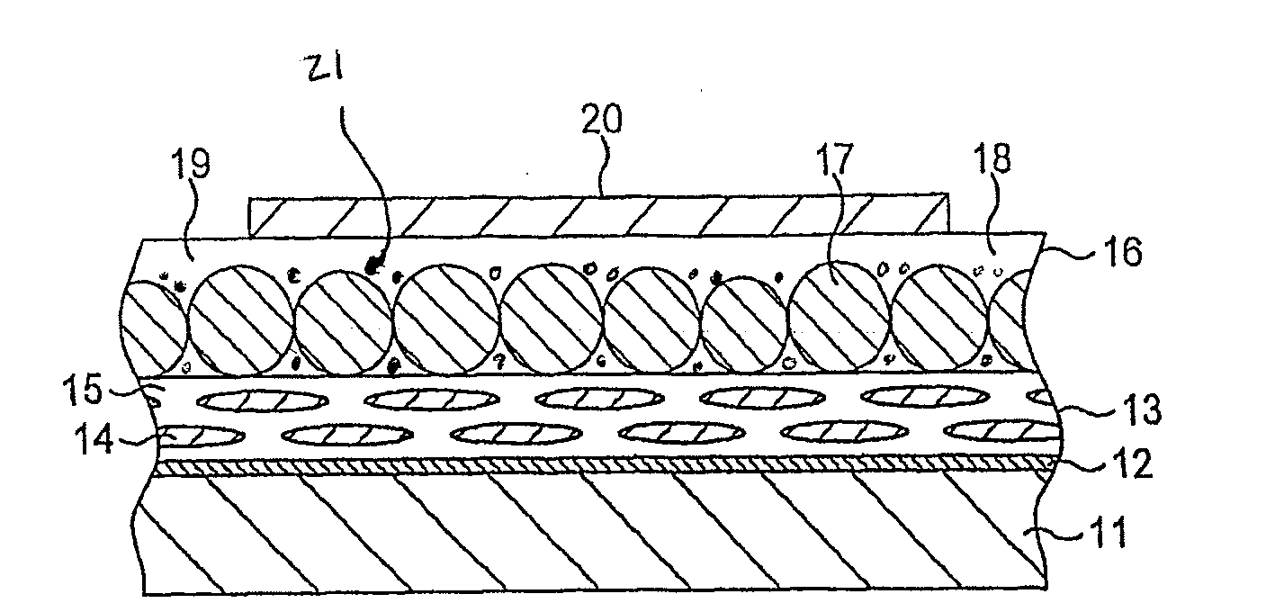
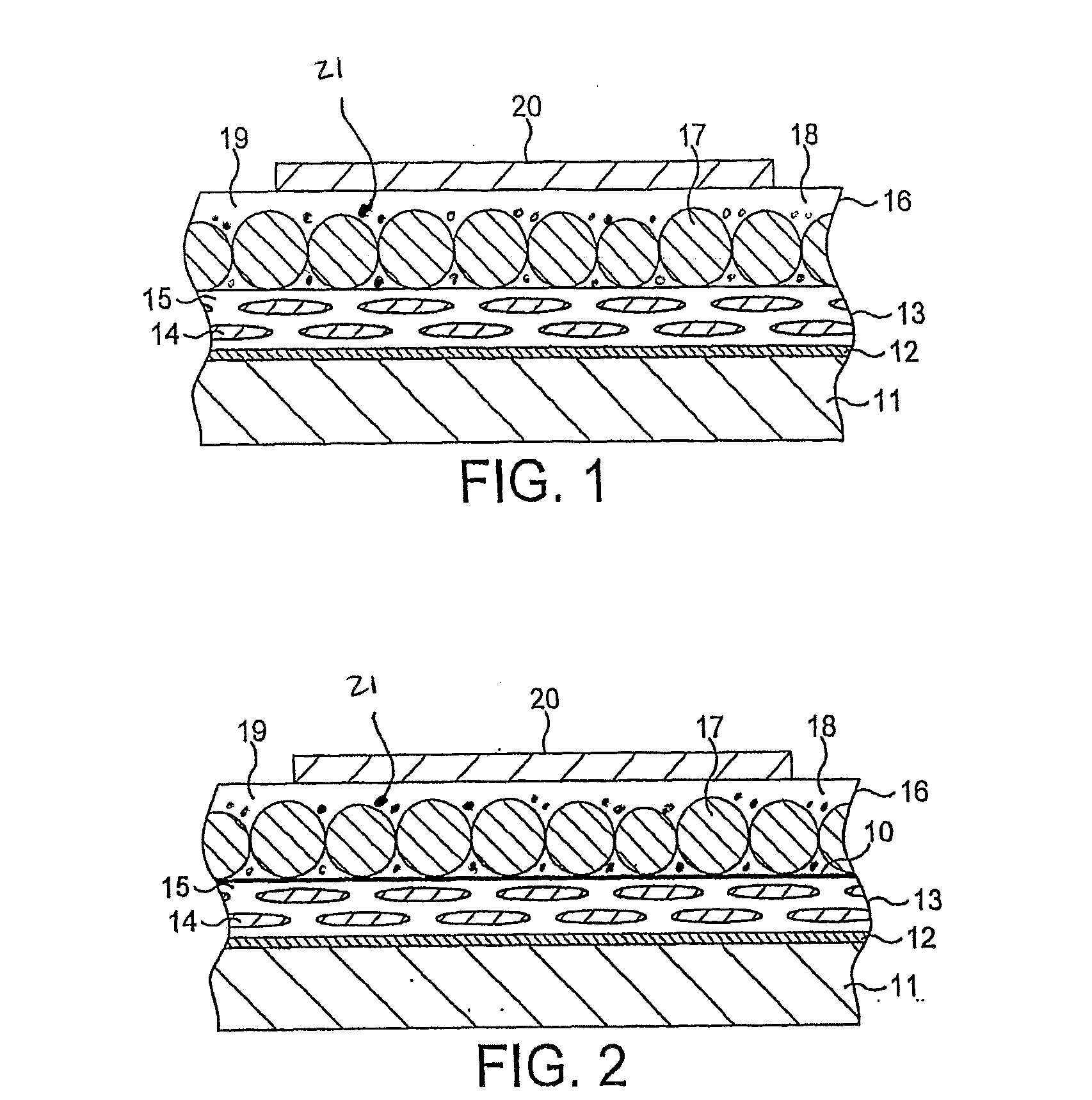
[0034]The structure of the first embodiment of the display of the invention depicted in FIG. 1 of the accompanying drawings can be seen to be, from front to back:

[0035]a relatively thick protective electrically-insulating transparent front layer (11; the substrate);

[0036]over the rear face of the substrate 11, a very thin transparent electrically-conductive film (12) forming the front electrode of the display;

[0037]covering the rear face of the front electrode 12, a relatively thin layer (13) of LC material (14) physically-stabilised by being dispersed within a supporting polymer matrix (15);

[0038]formed directly on, and covering the rear face of, the liquid crystal layer (13), a relatively thin electroluminescent layer (16);

[0039]over the rear face of the electroluminescent layer (16), a relatively thin optically-reflective electrically-insulating layer (19) of a relatively high dielectric constant material (in the Figure this layer is shown as a seamless extension of the electrolu...


PUM


Abstract

An electroluminescent layer for a light. The light includes a phosphor with a fluorescent pigment or dye.

Description

TECHNICAL FIELD[0001]This invention is concerned with electroluminescent displays and components thereof and, in particular, but not exclusively, displays that are electroluminescent / liquid crystal hybrids.BACKGROUND OF THE INVENTION[0002]Certain materials are electroluminescent—that is, they emit light, and so glow, when an electric field is generated across them. The first known electroluminescent materials were inorganic particulate substances such as zinc sulphide, while more recently-found electroluminescent materials include a number of small-molecule organic emitters known as organic light emitting diodes (OLEDs) and some plastics —synthetic organic polymeric substances—known as light-emitting polymers (LEPs). Inorganic particulates, in a doped and encapsulated form, are still in use, particularly when mixed into a binder and applied to a substrate surface as a relatively thick layer; LEPs can be used both as particulate materials in a binder matrix or, with some advantages, ...

Claims


Application Information

Patent Timeline
IPC IPC(8): H01J1/62
CPCC09K11/02G02F1/133603Y10S428/917G02F2001/133614H05B33/14G02F1/133621C09K11/08G02F1/133614
Inventor TYLDESLEY, WILLIAM FRANK
Owner MFLEX UK
Why Eureka
Try Eureka