Image pickup apparatus, control method for the same, and program for implementing the control method

a pickup apparatus and control method technology, applied in the direction of cameras, instruments, printers, etc., can solve the problems of difficult to obtain the optimal responsiveness appreciable decrease in operability, and hunting of the focus movement, so as to optimize the responsiveness of linear changes in focus to the operation of the ring member without sacrificing the operability of the ring member

Inactive Publication Date: 2009-11-05
CANON KK
View PDF18 Cites 19 Cited by
  • Summary
  • Abstract
  • Description
  • Claims
  • Application Information

AI Technical Summary

Benefits of technology

[0026]It is an object of the present invention to provide an image pickup apparatus and a control method for the same, which are capable of optimizing the responsiveness of linear changes in focus to operations of a ring member without sacrificing the operability of the ring member, while using a small-sized, low-cost ring member for manual operations, and a program for implementing the control method.
[0028]According to the image pickup apparatus of the first aspect, it is possible to optimize the responsiveness of linear changes in focus to operations of a ring member without sacrificing the operability of the ring member, while using a small-sized, low-cost ring member for manual operations.
[0029]Preferably, the image pickup apparatus comprises an optical lens group including the focus lens, a recording device that records a picked-up image picked up via the optical lens group onto a recording medium, and the responsiveness control device controls the responsiveness of linear changes in focus to the rotating operation state of the ring member detected by the detection device in accordance with the depth of focus that has been corrected based on a pixel density of the picked-up image and a pixel density of a recorded image to be recorded onto the recording medium.

Problems solved by technology

However, during a manual operation of the above-described conventional inner focus type lens unit, if the rotational speed of the focus ring 600 is detected based on the output signals of the ring rotation sensors 603, 604 and control is provided to adjust the focus according to the detected rotational speed, the rotational position of the focus ring 600 at which a focused state is achieved will differ according to whether the focus ring 600 is rotated at low speed or at high speed, resulting in the problem of the focus ring 600 having a different operational feel to a focus ring that is mechanically connected to the focus lens.
However, when the relationship between the focus movement amount the rotation amount of the focus ring 600 is made linear as above, it is difficult to obtain the optimal responsiveness of the focus movement amount to the rotation amount of the focus ring 600.
If the responsiveness is made lower, however, it is necessary to move the focus ring 600 even further when racking focus from a blurred state, leading to an appreciable decrease in operability.
Therefore, even if the ring responsiveness is not problematic for normal shutter speeds, at slow shutter speeds, if the photographer tries to change the focus in response to the focusing degree of displayed picked-up images, the photographer himself / herself will activate the servo, which results in hunting of the focus movement and hence in extreme difficulty in focusing.

Method used


Image

  • Image pickup apparatus, control method for the same, and program for implementing the control method
  • Image pickup apparatus, control method for the same, and program for implementing the control method
  • Image pickup apparatus, control method for the same, and program for implementing the control method

Examples


first embodiment

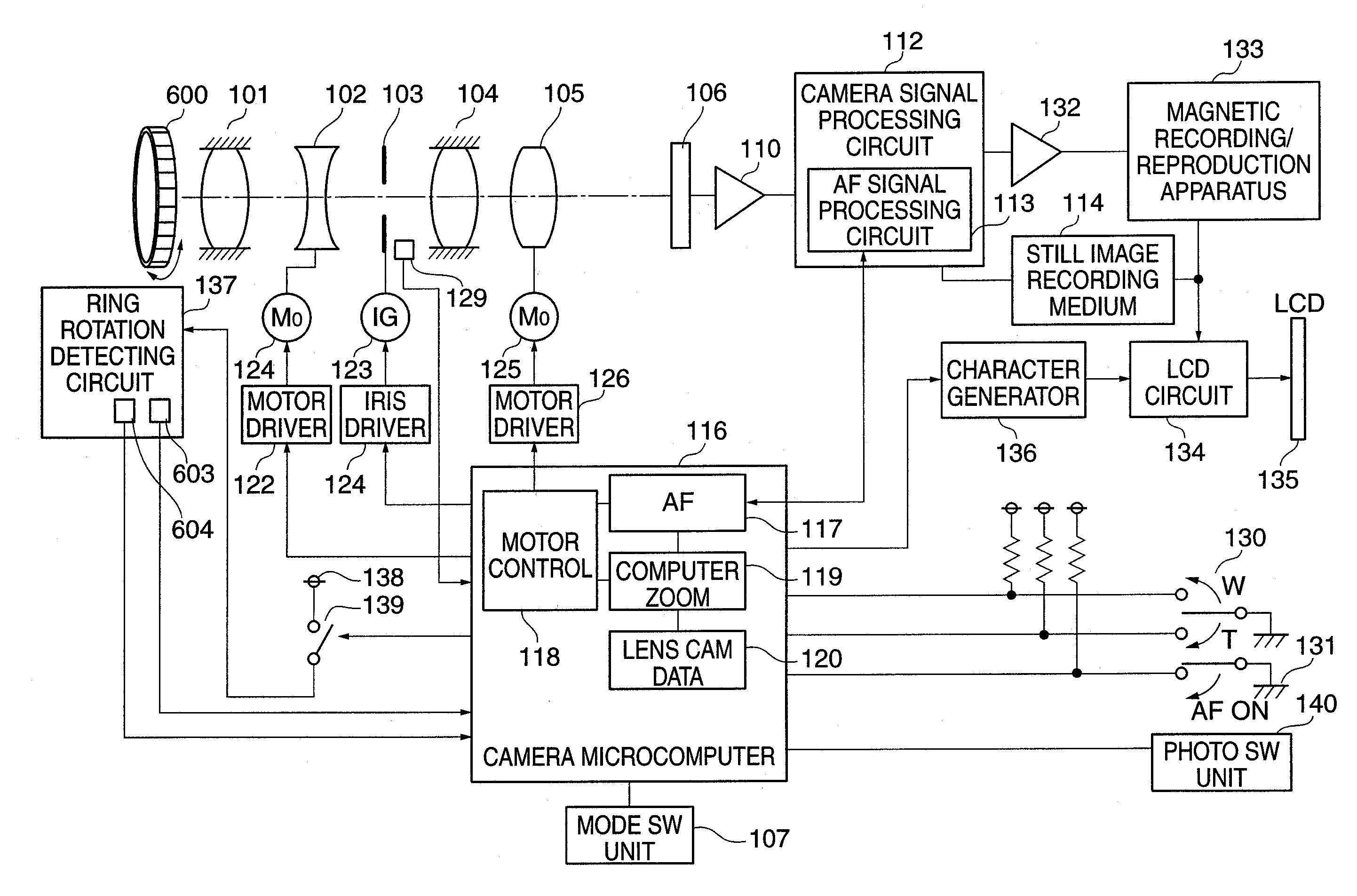
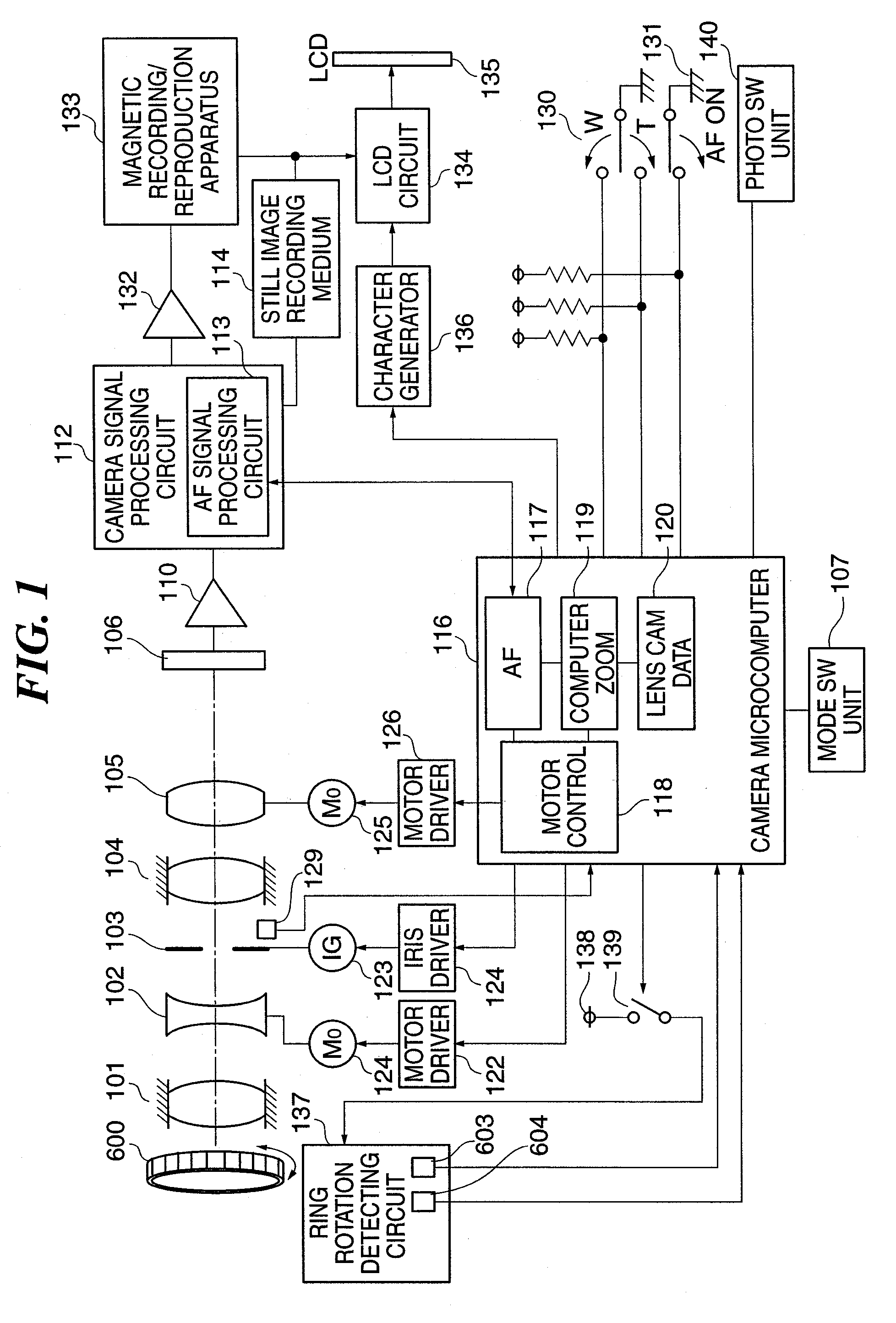
[0058]FIG. 1 is a schematic diagram showing the construction of an image pickup apparatus according to the present invention.

[0059]In FIG. 1, light from the subject passes through a fixed first lens group 101, a second lens group (hereinafter, “zoom lens”) 102 that carries out zooming, a diaphragm 103, a fixed third lens group 104, and a fourth lens group (hereinafter “focus lens”) 105 with a focus adjusting function and a compensating function for compensating for movement of a focal plane due to zooming, so that an image is formed on an image pickup element 106, such as a CCD (Charge Coupled Device).

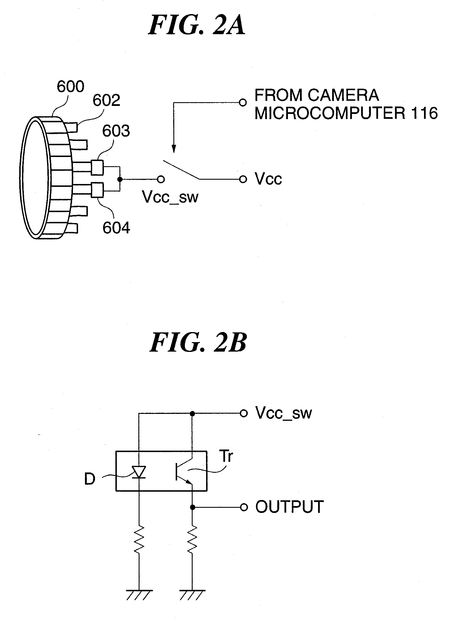
[0060]A focus ring 600, and ring rotation sensors 603, 604 shown in FIG. 1 are the same as described in the related art and have the same functions. A ring rotation detecting circuit 137 is equivalent to a circuit shown in FIG. 2, referred to later.

[0061]An optical image that has been formed on the image pickup element 106 by light that has passed through the respective lenses is subje...

second embodiment

[0101]Next, the present invention will be described.

[0102]According to the second embodiment, the responsiveness of the focus movement amount (change in focus) to rotating operation of the focus ring 600 is standardized according to the effective depth of focus based on the ratio of the pixel density of the picked-up image to the pixel density of a corresponding recorded image to be recorded on a recording medium.

[0103]For example, in recording still images onto a card medium or the like, all the pixels of the image pickup element 106 are recorded so that the depth of focus is equal to the diameter of permissible circle of confusion described with respect to the first embodiment. However, in recording moving images, only pixels stipulated by the DV format for a tape medium or the like are recorded, so that the effective depth of focus changes according to the ratio of the pixel density of the picked-up image to the pixel density of a corresponding recorded image to be recorded on th...

third embodiment

[0118]Focusing control in response to rotating operation of the focus ring 600 will be described with reference to flowchart in FIGS. 8A and 8B. It should be noted that steps in the flowchart in FIGS. 8A and 8B that are the same as in the flowcharts in FIGS. 4, 7A and 7B are designated by identical step numbers.

[0119]Steps S702 to S802 in FIG. 8B are for determining the responsiveness of the focus movement amount (change in focus) to a rotating operation of the focus ring 600, with processing from the steps S702 to S414 being for determining the effective depth of focus in accordance with the pixel density of a recorded image to be recorded on a recording medium (this is the same as in the second embodiment) and processing in the step S802 being for determining the focusing speed in accordance with the effective depth of focus and the exposure time.

[0120]In the step S802, an equation for calculating the focusing speed in the step S802 is used, i.e. Equation 5 given below, which is ...


PUM


Abstract

An image pickup apparatus which is capable of optimizing the responsiveness of linear changes in focus to operations of a ring member without sacrificing the operability of the ring member, while using a small-sized, low-cost ring member for manual operations. The rotating operation state of a focus ring 600 is detected by ring rotation sensors 603, 604. A camera microcomputer 116 causes a focus lens 105 to be moved and stopped in an optical axis direction thereof based on results of the detection by the ring rotation sensors 603, 604. The camera microcomputer 116 controls the responsiveness of linear changes in focus to the rotating operation state of the ring member detected by the ring rotation sensors 603, 604 in accordance with at least the depth of focus.

Description

[0001]This is a continuation of U.S. patent application Ser. No. 10 / 803,637 filed Mar. 18, 2004 which is based on and claims priority from Japanese Application No. 2003-078440 filed on Mar. 20, 2003, the contents of each are incorporated herein in their entirety by reference.BACKGROUND OF THE INVENTION[0002]1. Field of the Invention[0003]The present invention relates to an image pickup apparatus, a control method for the same, and a program for implementing the control method, and in particular to an image pickup apparatus equipped with a function for manually moving a focusing lens, a control method for the same, and a program for implementing the control method.[0004]2. Description of the Related Art[0005]Conventionally, in consumer integrated-lens cameras, inner focus type lens units that can realize cost reductions, system simplifications, and reductions in the size and weight of a lens barrel have become predominant.[0006]FIG. 10 is a schematic diagram showing the construction ...

Claims


Application Information

Patent Timeline
Patent Type & Authority Applications(United States)
IPC IPC(8): H04N5/232G02B7/08G03B3/00G02B7/10
CPCH04N5/23212G02B7/102G03B13/32H04N23/672H04N23/959H04N23/651
Inventor OKAWARA, HIROTO
Owner CANON KK
Why Eureka
Try Eureka