Eureka AIR delivers breakthrough ideas for toughest innovation challenges, trusted by R&D personnel around the world.

Process for producing optical functional film, optical functional film, polarizing plate, optical element and image display device

Inactive Publication Date: 2009-11-05
NITTO DENKO CORP
View PDF2 Cites 2 Cited by
  • Summary
  • Abstract
  • Description
  • Claims
  • Application Information

AI Technical Summary

Benefits of technology

[0013]According to the present invention, by having the distance D2 between the leading end of the downstream die lip and the substrate film being 50 μm or greater, it is possible to prevent adhesion or solidification of polyimide at a leading end of the downstream die lip and efficiently prevent streaky coating unevenness in the traveling direction of the substrate film.
[0014]Furthermore, by providing stepped arrangement of 0<D1−D2≦200 μm to the leading ends of the pair of die lips, a coating liquid is applied through these leading ends of the die lips as it is enlarged or increased in volume towards the upstream side of the substrate film, so that the contacting state between the coating liquid and the substrate film is well maintained, and coating unevenness in the widthwise direction of the substrate film due to pulsations of the coating liquid or fluctuation in the traveling speed of the substrate film.
[0015]According to the process for producing an optical functional film of the present invention, in combination with the above functions and advantages, a polyimide-containing coating liquid, which is easy to cause appearance defect when using a die coater in a conventional method, is possible to be applied with an even thickness while providing a thin layer, and thus a film having less appearance defect can be produced.
[0011]Furthermore, according to the present invention, there are provided a polarizing plate, an optical element and an image display device, each having the aforesaid optical functional film.

Problems solved by technology

However, in a method of using a low viscosity coating liquid, resin flow occurs locally on a substrate film with the coating liquid applied thereon during the shift from an application step, in which the coating liquid is applied onto the substrate film, to a drying step; and when the resin is cured with resin flow remained, bright spots due to repellent action on the coated surface, interference unevenness due to the difference in thickness of a resin layer at local areas, uneven retardation or the like may occur, which causes a problem that appearance defect is easy to occur.
Therefore, according to the conventional application method, it is difficult to form on a substrate film a resin layer without defect appearance.
Especially, polyimide has been attracting attention because of its very excellent transparency, orientation and stretchability; however when a coating liquid containing the polyimide is to be applied by the conventional method, that is, when the viscosity of the coating liquid containing the polyimide is merely lowered, a good appearance may not be obtainable and furthermore there is a problem that appearance defect inherent to the polyimide may occur.

Method used


Image

  • Process for producing optical functional film, optical functional film, polarizing plate, optical element and image display device
  • Process for producing optical functional film, optical functional film, polarizing plate, optical element and image display device
  • Process for producing optical functional film, optical functional film, polarizing plate, optical element and image display device

Examples


example 1

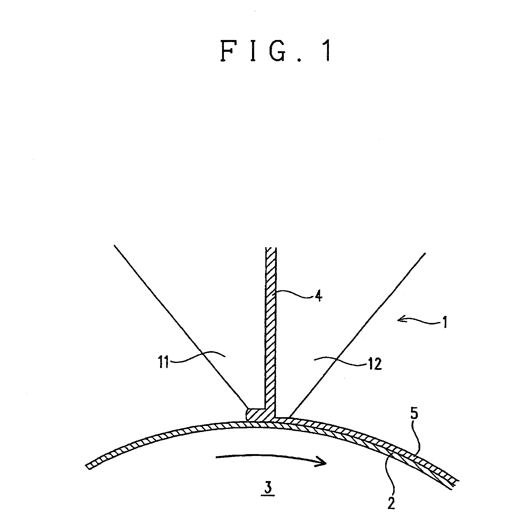
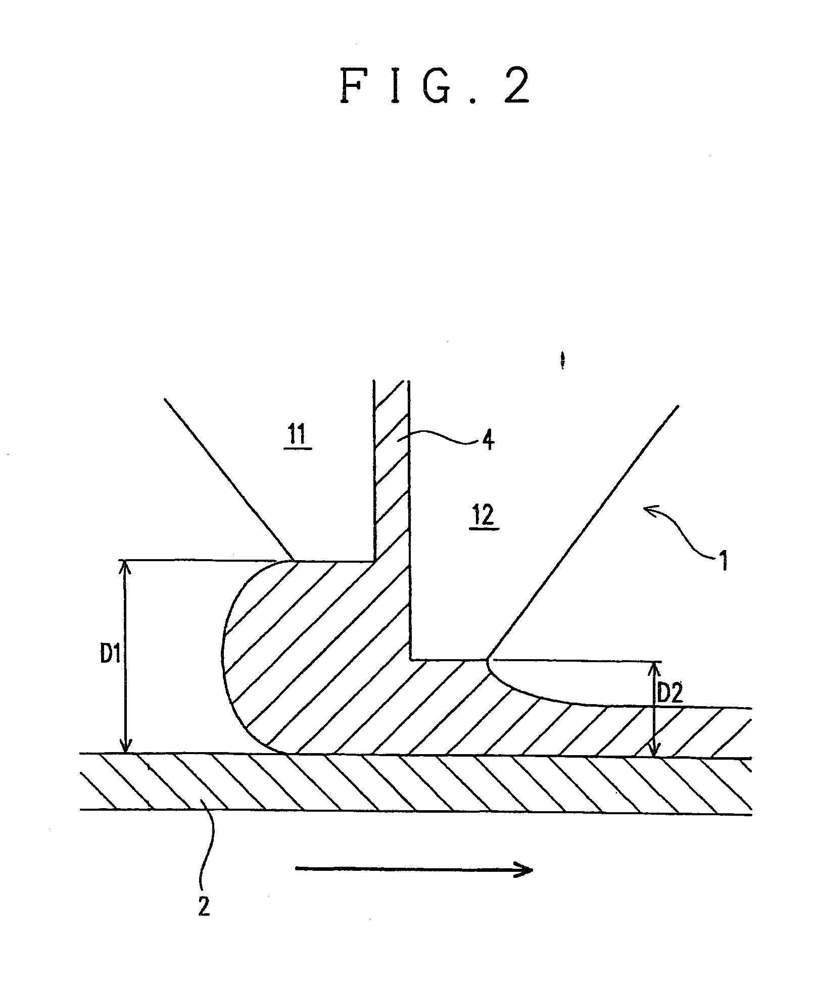
[0116]10% by weight of polyimide (the aforesaid formula (6), weight-average molecular weight Mw=140,000) is dissolved in methyl isobutyl ketone to prepare a polyimide solution having a viscosity of 200 mPa·sec. The polyimide solution is used as a coating liquid and this coating liquid is applied onto a polyethylene terephthalate film as a substrate film (thickness: 75 μm) that is kept moving at a moving speed of 20 m / min, by using a slit die coater (D2=100 μm, D1−D2=50 μm, die lip leading end width: 0.8 mm) having the structure as illustrated in FIG. 2, and after application, it was dried at 120° C. for 3 minutes. Thus, a test film with a polyimide layer having a thickness of 3 μm was produced.

[0117]FIG. 6 is a photograph of a top view of the test film produced in Example 1. As illustrated in FIG. 6, it has been found that the produced test film as a whole has no interference unevenness observable with eyes and has a very excellent appearance, although a gentle streaky interference ...

example 2

[0118]A test film with a polyimide layer having a thickness of 3 μm was produced in the same manner as in Example 1, except that a slit die coater having D2=100 μm, D1−D2=30 μm and a die lip leading end width of 0.8 mm is used.

[0119]FIG. 7 is a photograph of a top view of the test film produced in Example 2. As illustrated in FIG. 7, it has been found that interference unevenness resulting from the thickness unevenness of the polyimide layer is almost not found in the produced test film, and a film having a good appearance is produced.

example 3

[0120]A test film with a polyimide layer having a thickness of 3 μm was produced in the same manner as in Example 1, except that a slit die coater having D2=60 μm, D1−D2=10 μm and a die lip leading end width of 0.8 mm is used.

[0121]FIG. 8 is a photograph of a top view of the test film produced in Example 3. As illustrated in FIG. 8, it has been found that the produced test film as a whole has no interference unevenness observable with eyes and has a very excellent appearance, although a gentle streaky interference unevenness resulting from the thickness unevenness of the polyimide layer is partly and slightly caused.

Comparative Example 1

[0122]An attempt was made to produce a test film in the same manner as in Example 1, except that a slit die coater having D2=100 μm, D1−D2=−20 μm and a die lip leading end width of 0.8 mm is used.

[0123]However, a coating liquid discharged through the leading ends of the die lips could not be applied as a coating liquid onto a substrate film.


PUM

PropertyMeasurementUnit
Thicknessaaaaaaaaaa
Percent by massaaaaaaaaaa
Radiusaaaaaaaaaa

Abstract

A process for producing an optical functional film having a polyimide layer is provided, which includes an application step of applying a coating liquid containing polyimide and having a viscosity γ of 100<γ<3000 mPa·s on a substrate film by a die coater having an upstream die lip and a downstream die lip, thereby forming a polyimide layer on the substrate film, in which D2≧50 μm and 0<D1−D2≦200 μm are satisfied, in which D1 represents a distance between a leading end of the upstream die lip and the substrate film and D2 represents a distance between a leading end of the downstream die lip and the substrate film.

Description

FIELD OF THE INVENTION[0001]The present invention relates to a process for producing an optical functional film and an optical functional film, as well as a polarizing plate, an optical element and an image display device, each having the optical functional film.BACKGROUND OF THE INVENTION[0002]In recent years, many liquid crystal display devices having excellent characteristics, such as low-profile, light-weight, and low power consumption characteristics are used as display devices of such as TV sets and personal computers. The liquid crystal display device of this type uses an optical functional film having resin layers exhibiting various optical performances such as polarization, optical compensation and antireflection, as well as a liquid crystal layer as a main element.[0003]When unevenness in thickness is caused in a resin layer of the optical functional layer, interference unevenness is caused in transmitted light, which in turn deteriorates the performance of the optical fun...

Claims


Application Information

Patent Timeline
IPC IPC(8): B32B5/00B05D5/06B05D1/26B05D7/04B05D7/24B29C41/24B29C41/34B29C41/36B29C41/38B29K79/00B29L7/00G02B1/10G02B1/111G02B5/30
CPCC08J5/18Y10T428/265G02B5/3033C08J2379/08B05D7/04G02B5/30B05D7/24B05D1/26
Inventor KONDOU, SEIJIYOSHIDA, KENTAROUNAGATAKE, WATARUSHIBATA, SHOUJI
Owner NITTO DENKO CORP
Why Eureka
Eureka Blog
Learn More