Non-reciprocal component and method for making and using the component in a mobile terminal

Active Publication Date: 2009-11-05
ST ERICSSON SA
View PDF5 Cites 0 Cited by
  • Summary
  • Abstract
  • Description
  • Claims
  • Application Information

AI Technical Summary

Benefits of technology

[0014]The invention is based on the thought that by using in-plane magnetization of a ferrite substrate the height problem mentioned above will be solved. The proposed non-reciprocal component is based on a configuration using in-plane magnetization of the ferrite substrate. To reduce the required length and maintain the non-reciprocal behavior, it is further proposed to arrange metal lines in such a way that they are running at least one time from one side of the ferrite substrate to the opposite other side of the ferrite substrate and back. This course or track of the metal lines on the ferrite substrate will reduce the total length of the component. However the two metal lines have to be arranged interlaced on their track on the ferrite substrate. To achieve the required non-reciprocal behavior the first metal line and the second metal line are formed like meander loops, wherein the meander loops are interlaced. However the metal lines have to be isolated from each other especially in the area of the loop at the end of the ferrite substrate. By arranging both metal lines in that way a non-reciprocal behavior will be created. Both metal lines have two ports located at the ends of a metal line. By interlacing the meander loops, a 4-port circulator is provided. A 4 port circulator acts as a one way component allowing the microwave to pass only in one direction, e.g., from port 4 to port 1. The microwave will be damped in all other directions. The non-reciprocal component enables a considerable miniaturization compared to a component based on only two elongated metal lines arranged in parallel. In contrast to commercially available components of this type this non-reciprocal circuit element is perfectly suited for integration using multilayer technology (like e.g., LTCC). The employment of such a monolithic approach can reduce the production costs significantly.
[0015]Since in-plane magnetization is used the magnetic field strength to be applied needs to be very small in comparison to the common design with the perpendicular magnetic field. Using in-plane magnetization only small demagnetization effects will appear, so the magnetic field generated by the permanent magnets needs to be very small. This will further reduce the dimensions of the permanent magnets and therefore of the whole non-reciprocal component.
[0016]By providing the two metal lines in a plurality of meander loops, which are interlaced, the non-reciprocal behavior could be improved.
[0017]In a preferred embodiment of the present invention the ports of the metal lines could be located on both sides of the ferrite substrate. This may simplify the layout of the component in certain cases. Further, the flexibility in the arrangement of the ports in relation to the surrounding components is increased.

Problems solved by technology

The high cost of the isolator is accepted, since a modified system architecture which does not need an isolator would be very difficult to design and not reliable.
The high production costs of state of the art non-reciprocal RF components are due to their very complex internal set up.
All parts of the non-reciprocal component have to be assembled during a complicated production process.
Unfortunately, integrated solutions for non-reciprocal RF components are up to now not available.
Since the common design of the non-reciprocal RF components uses a magnetic field, which is directed perpendicular to the propagation direction of the microwave, it was not possible to integrate such components, particularly because the permanent magnets have to be placed below and / or above the ferrite material.
This results in a large height of the component.
Since the required permanent magnetic field increases with the working frequency, the height problems become particularly severe in the high frequency range.
At high working frequencies, this problem becomes more and more pronounced.
Integration of such a design is therefore not feasible.
However, non-reciprocal components, which utilize this in-plane magnetization, are not available.
The required length of the metal lines would reduce the commercial value of the design.

Method used


Image

  • Non-reciprocal component and method for making and using the component in a mobile terminal
  • Non-reciprocal component and method for making and using the component in a mobile terminal
  • Non-reciprocal component and method for making and using the component in a mobile terminal

Examples


Embodiment Construction

[0035]In the following, the various exemplary embodiments of the invention are described. Although the present invention is applicable in a broad variety of applications it will be described with the focus put on a 4 port circulator used in the area of microwave technology. A further field for applying the invention might be the use as isolator.

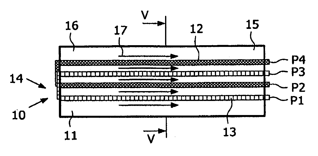
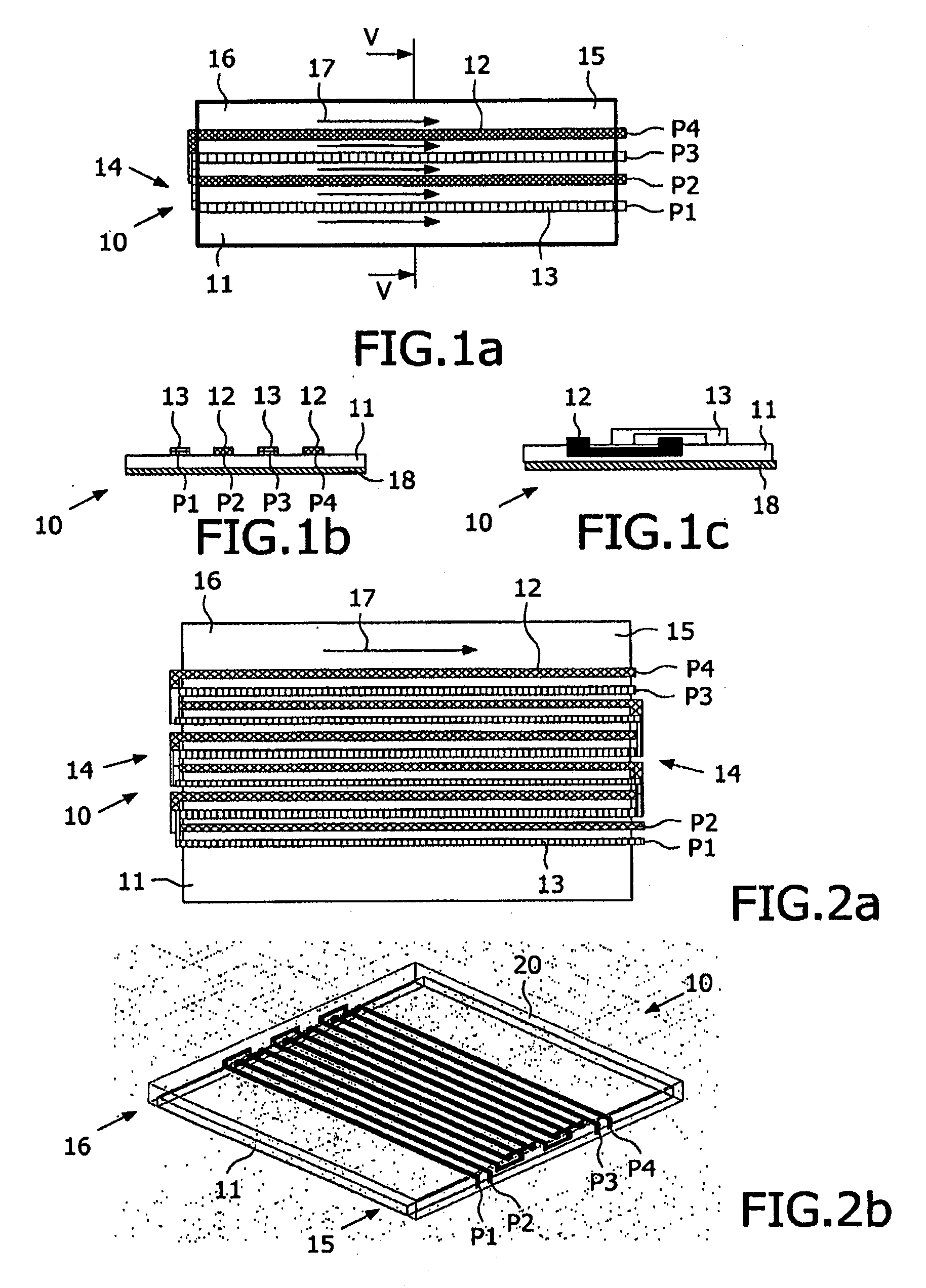
[0036]FIG. 1a represents a top view of a non-reciprocal component 10, 4-port circulator embodiment according the present invention. A ferrite substrate 11 having a first side or end 15 and an opposing end 16. Two metal lines 12, 13 are printed on the ferrite substrate 11. The metal line 12 runs from side 15 to the opposing side 16 and back to side 15 just as metal line 13. Each metal line forms one meander loop. The meander loops of metal line 12 and of metal line 13 are interlaced to each other. Each metal line 12, 13 has two ports P1, P2, P3, P4. The first metal line 12 is connected to the ports P2 and P4. The second metal line 13 has the p...


PUM

PropertyMeasurementUnit
Temperatureaaaaaaaaaa
Dielectric polarization enthalpyaaaaaaaaaa
Magnetic fieldaaaaaaaaaa

Abstract

The invention relates to a non-reciprocal component comprising: a ferrite substrate having a first side and an opposing second side located on a ground layer, a first metal line and a second metal line are located on the ferrite substrate in parallel to each other. To provide a non-reciprocal component having small dimensions and which could be integrated. The ferrite substrate is magnetized parallel to the metal lines and each of the metal lines is running at least from one side of the ferrite substrate to the other side and back forming thereby at least one meander loop, wherein the loops are interlaced to each other and the metal lines are isolated in an area of the loop.

Description

CROSS-REFERENCE TO RELATED APPLICATION[0001]This application is a continuation that claims priority under 35 U.S.C. § 120 to currently pending U.S. patent application Ser. No. 11 / 658,229, entitled “INTEGRATED NON-RECIPROCAL COMPONENT COMPRISING A FERRITE SUBSTRATE,” filed Jan. 22, 2007, assigned to the same assignee as the present application, and incorporated herein by reference in its entirety.BACKGROUND[0002]1. Technical Field[0003]The invention relates to a non-reciprocal component comprising a ferrite substrate having a first and an opposing second side located on a ground layer, wherein a first metal line and a second metal line are located on the ferrite substrate in parallel to each other. The invention relates further to an integrated circuit including a non-reciprocal component and to a circulator.[0004]2. Description of the Related Art[0005]Non-reciprocal components are used especially in microwave technology, which has become very important during the last years. Various...

Claims


Application Information

Patent Timeline
IPC IPC(8): H04B1/04H01P1/38H01L21/00H01P11/00H01P1/387
CPCY10T29/49016H01P1/38
Inventor PIETIG, RAINERCAO, MENG
Owner ST ERICSSON SA
Why Eureka
Try Eureka