Heat leaks into the cryogen vessel will evaporate the cryogen which might then be lost from the
magnet system as boil-off.
During transportation of an already assembled system, the refrigerator cooling the one or more shields and / or the cryogen vessel is inactive, and is incapable of diverting the
heat load from the cryogen vessel.
This in turn means a relatively high level of heat input during transportation, leading to loss of cryogen liquid by boil-off to the
atmosphere.
An
advantage of transporting the system before installing the refrigerator is that the material typically used to make good
thermal contact when the refrigerator is installed,
Indium, although nominally making the refrigerator removable, can lead to problems with getting as good a
thermal contact when the refrigerator is re-installed owing to parts of the original material remaining on the surfaces.
The refrigerator has a limited cooling capability and there can be long delays before the
radiation shield is cold enough for the
superconducting magnet to be energized.
The thermal shield is typically poorly coupled to this source of cooling and so the temperature of the
radiation shield increases during the magnet transportation, increasing the
thermal load on the
Helium vessel due to
radiation.
As is well known in the art, a difficulty arises when first cooling such a
cryostat from ambient temperature.
While this may be acceptable when using an inexpensive, non-polluting, essentially inexhaustible cryogen such as
liquid nitrogen, it is not considered acceptable to use this approach for a working cryogen such as
helium, which is relatively costly to produce, or to re-liquefy, and is a finite resource.
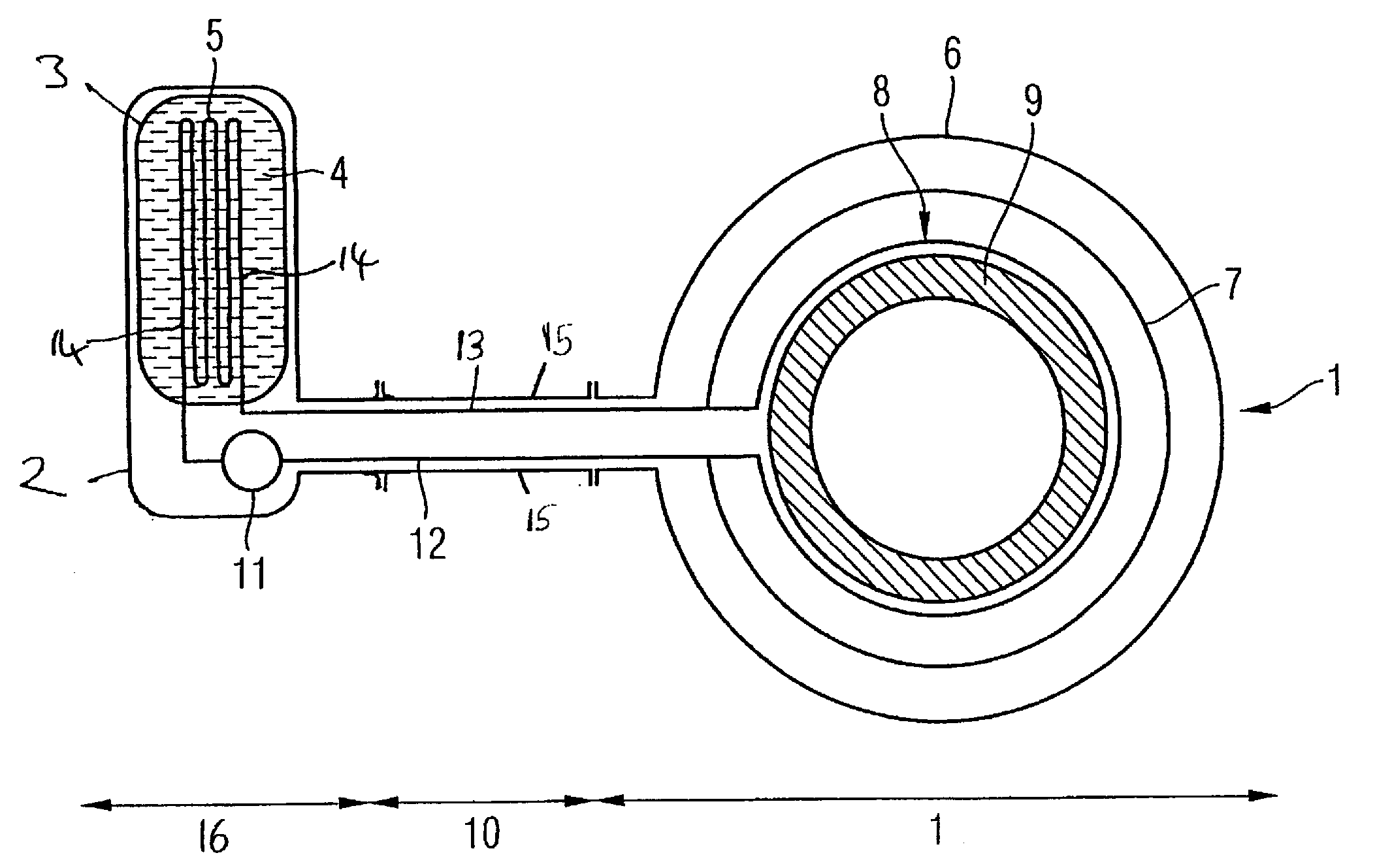
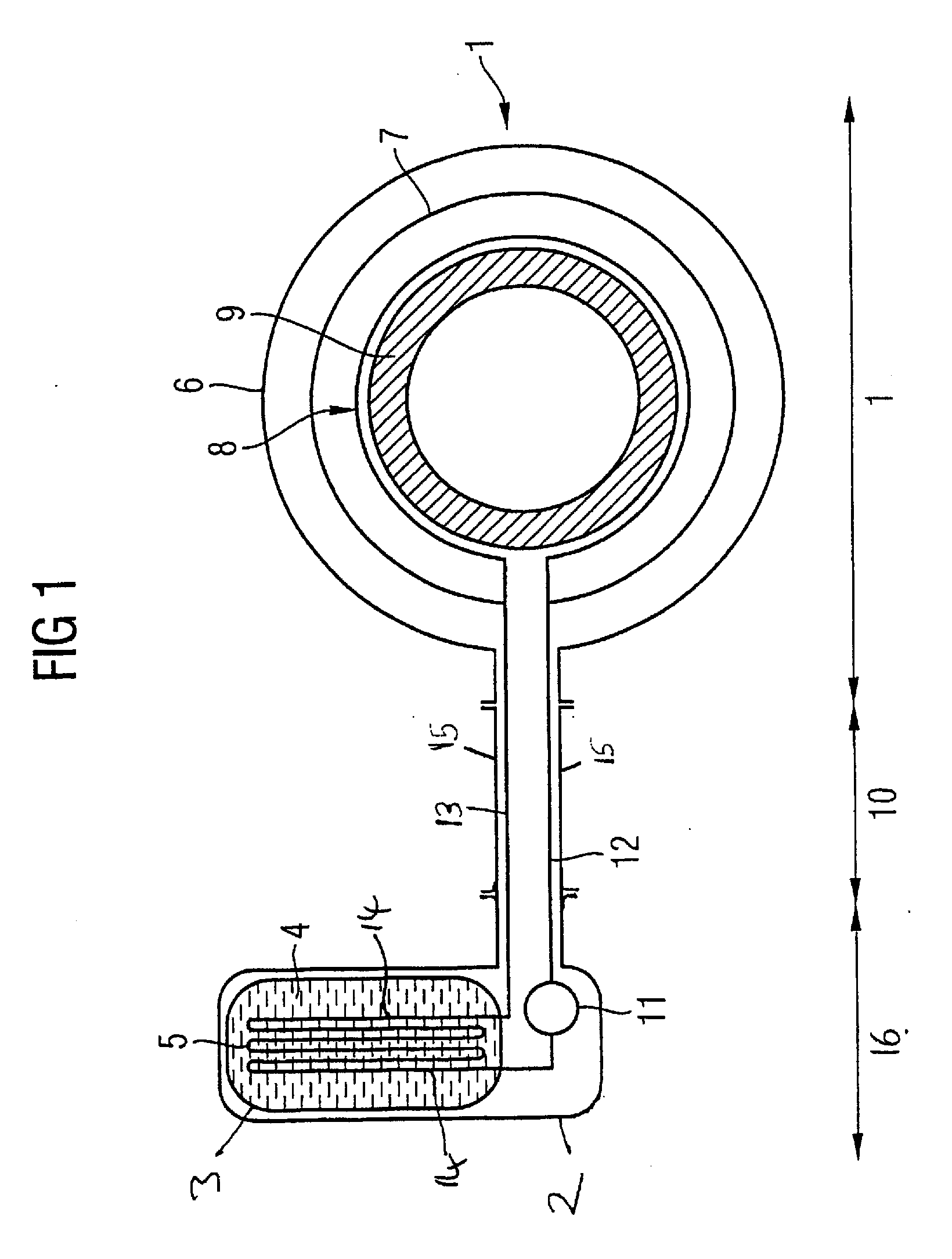
Although the material of the cryogen vessel itself quickly cools on addition of a cryogen, an issue arises with the cooling of the
thermal radiation shield(s).
1) Operating the refrigerator to cool the
thermal radiation shields has the
disadvantage that any sacrificial cryogen within the cryogen vessel would need to be removed beforehand, since otherwise the sacrificial cryogen will be liquefied or frozen in the cryogen vessel.
The refrigerator is then used to cool the
thermal radiation shield from 200 K to 50 K. This process takes approximately 6 days, during which time approximately 200 liters of
liquid helium are typically lost in boil off, at a significant cost.
While the financial cost of the lost
helium is significant, the length of time required for cooling is also troublesome.
The pressure to ship completed cryostats and magnet systems to customers as soon has possible has led to the refrigerator re-condensing test being omitted from some
testing protocols.
This, in turn, can lead to difficulties later.
For example, if any of these cryostats or magnet systems exhibit boil-off issues on, or after, installation, rapid problem diagnosis and correction will be hindered as their baseline cryogenic performance is unknown.
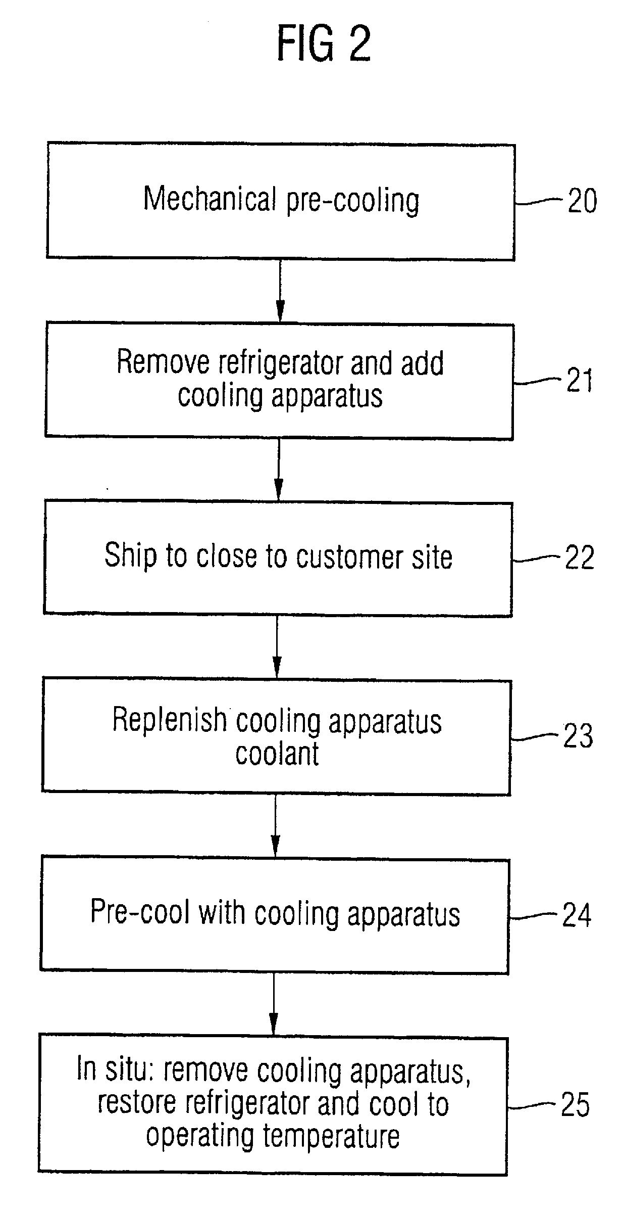
A particular problem after preparation and testing of the
cryostat for dispatch to a customer site is the need to keep the system cool in transit, without an operational refrigerator.

